


DEFINITY Enterprise Communications Server Release 6
Installation and Test for Multi-Carrier Cabinets
555-230-112
Issue 5
May 1998
Cable Ductwork
Page C-11
C
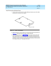
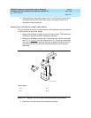
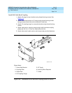
5. Set the shielded cross-aisle trough cover ("H") on top of the trough with its
side walls outside of the walls of the trough, and press it down until it
completely covers the trough.
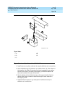
Mating Cross-Aisle Risers to Old Cabinet Risers
The new shielded ductwork is constructed so cross-aisle risers can be attached
to cabinet risers of the former design.
1. Remove the shielded coupling from the old cabinet riser. This assembly is
illustrated in the older system’s installation document.
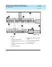
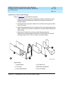
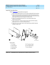
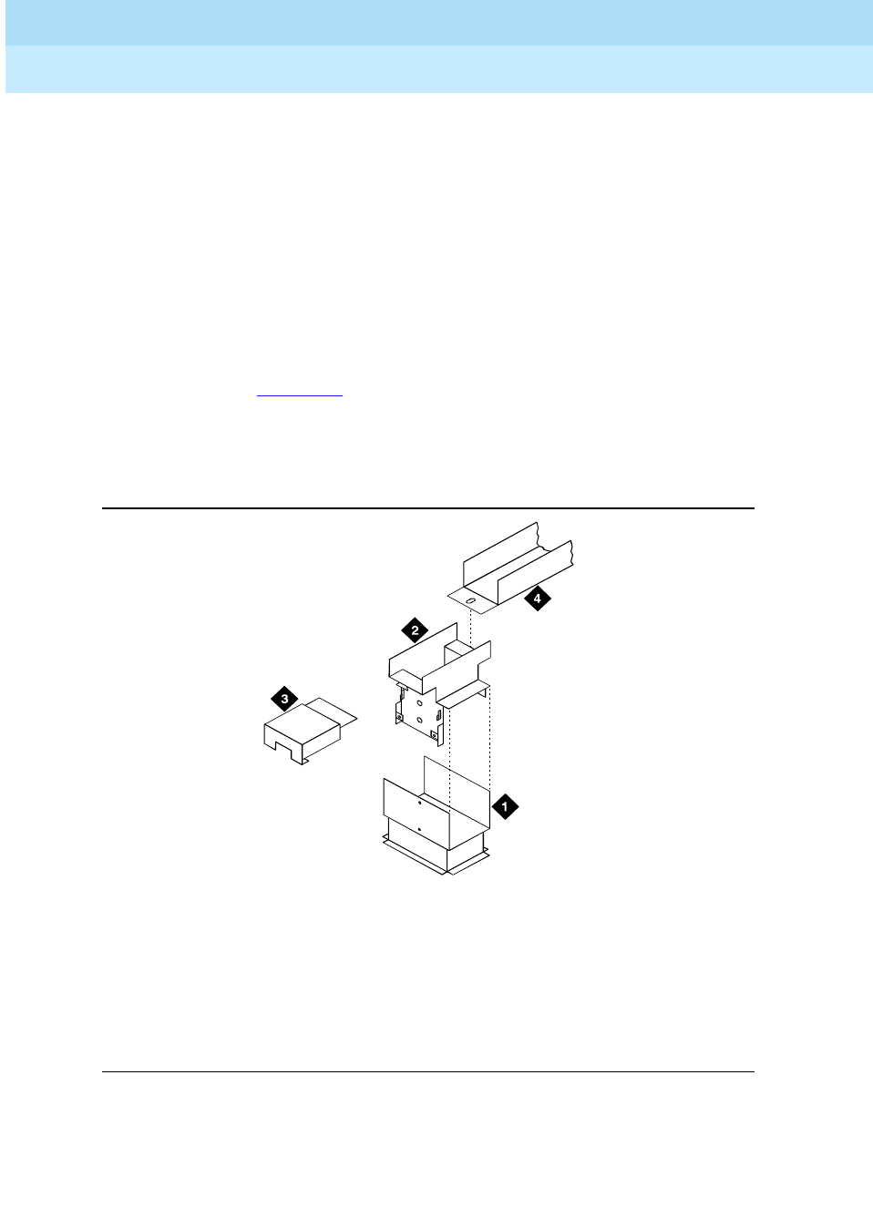
2. Replace the shielded coupling with a cross-aisle riser. Set the cross-aisle
riser (“C” in Figure C-6
) on the cabinet riser (“A”). Position the cross-aisle
riser so the two holes on the back wall line up with the holes on the back
wall of the cabinet riser. Bolt the two pieces together at the holes just
described.
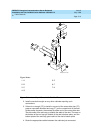
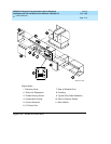
Figure C-6. Mating Cross-Aisle Risers to System 85-R2 Cabinet Risers
3. Assemble cross-aisle ductwork as already described.
Figure Notes
1. A
2. C
3. F
4. G
oldduct KLC 071796