


DEFINITY Enterprise Communications Server Release 6
Installation and Test for Multi-Carrier Cabinets
555-230-112
Issue 5
May 1998
Install Telecommunications Cabling
Page 2-45Patch Cord/Jumper Installation and Administration
2
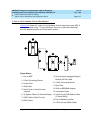
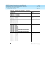
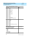
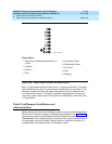
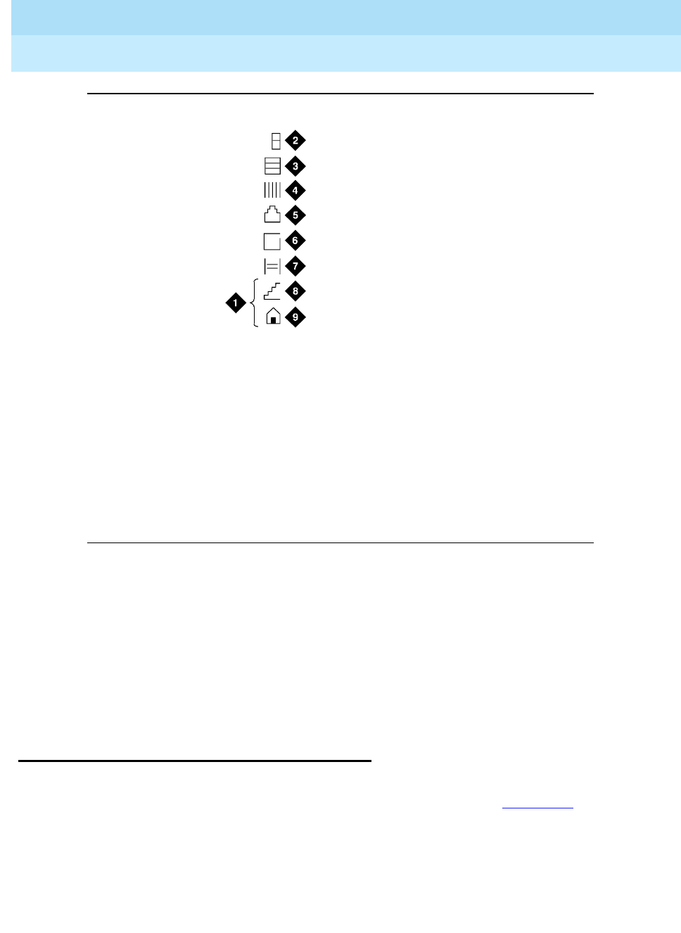
Figure 2-24. Label Graphic Symbols and Nomenclature
Each 110-type label identifies 2 rows on the 110-type terminal block. The upper
half identifies the row above it and the lower half identifies the row below it. The
labels are inserted into the clear plastic designation strips furnished with the
110-type terminal blocks. The strip is snapped in place between the terminal
block rows. Label code number 220A (comcode 103970000) contains all of the
110-type labels.
Patch Cord/Jumper Installation and
Administration
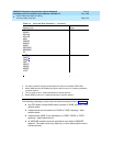
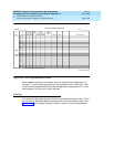
Before starting the patch cord installation, obtain a copy of the Port Assignment
Record forms from the customer or marketing representative. See Figure 2-25
.
These forms contain the port assignments and identify the extension numbers
(Terminal No.) of the telephones/voice terminals. Enter the jack assignments at
the equipment room and indicate if adjunct power is required and where it is
provided (MDF, site/satellite closet, or information outlet).
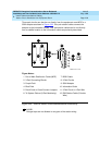
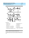
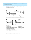
Figure Notes:
1. Write Floor or Building Identification on
Label
2. Cabinet
3. Carrier
4. Slot
5. Information Outlet
6. Site/Satellite Closet
7. Tie Circuit
8. Floor
9. Building
r758422i LJK 050996