


DEFINITY Enterprise Communications Server Release 6
Installation and Test for Multi-Carrier Cabinets
555-230-112
Issue 5
May 1998
Install and Wire Telephones and Other Equipment
Page 5-26TN1654 DS1 Converter (Release 6r Only)
5
Port Carrier
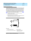
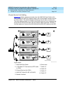
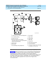
1. Install the TN1654 in any slot in a Port Carrier, next to a TN570C
Expansion Interface circuit pack.
2. On the backplane, connect a 14-inch (35.56 cm) “Y” cable from the
TN1654 to the Expansion Interface circuit pack. See Figure 5-12
.
!
CAUTION:
The “Y” cable used with the TN1654 is different than the “Y” cable
used with the TN574. These cables are NOT interchangeable.
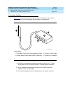
3. Connect an H600-348 Quad cable to the remaining end of the “Y” cable.
4. Skip to ‘‘
Channel Service Unit Cabling’’.
Switch Node Carrier
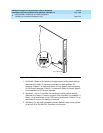
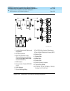
Up to 2 TN1654 circuit packs can be installed in a Switch Node Carrier.
1. Install the TN1654 in any slot in the Switch Node Carrier, next to a TN573B
Switch Node Interface circuit pack.
2. On the backplane, connect a 14-inch (35.56 cm) “Y” cable from the
TN1654 to the Switch Node Interface circuit pack. See Figure 5-12
.
!
CAUTION:
The “Y” cable used with the TN1654 is different than the “Y” cable
used with the TN574. These cables are NOT interchangeable.
3. Connect an H600-348 Quad cable to the remaining end of the “Y” cable.
4. Skip to ‘‘
Channel Service Unit Cabling’’.
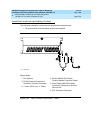
Port Carrier to Switch Node Carrier
When the TN1654 is located in the Port Carrier and the Switch Node Interface
circuit pack is located in the Switch Node Carrier, connect a 70” (177.8 cm) “Y”
Cable between the 2 circuit packs.
!
CAUTION:
The “Y” cable used with the TN1654 is different than the “Y” cable used with
the TN574. These cables are NOT interchangeable.
1. Connect an H600-348 Quad cable to the remaining end of the “Y” cable.