


DEFINITY Enterprise Communications Server Release 6
Installation and Test for Multi-Carrier Cabinets
555-230-112
Issue 5
May 1998
Install and Wire Telephones and Other Equipment
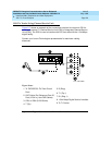
Page 5-12Auxiliary Connector Outputs
5
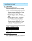
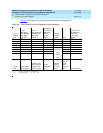
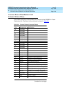
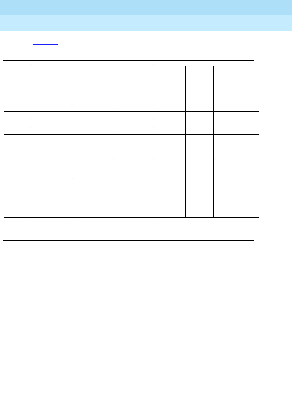
Tab le 5- 3 provides port circuit pack and telephone pin designations.
Table 5-3. Port Circuit Pack and Telephone Pin Designations
Pin on
Modular
plug
4-wire;
302C, 8403,
8410, 8411B/D,
8434, 603E,
9403, 9434
2-wire;
302C, 8403, 8410,
8411B/D, 8434,
603E, 9403,
9410, 9434
8510T Basic
Rate Interface
(BRI) (with
adjunct
speaker
phone)
Analog
Station,
Modem NT1
Z3A1 & Z3A2
Asynchronous
Data Units
(ADU), Data
Modules
1TXT TXT
2 TXR T TXR
3 PXT TXT R PXT
4TPXRT
5RPXTNo
Connection
(4-pin
modular
jack)
R
6PXR TXR PXR
7 -48VDC (-48VDC) (-48VDC) -48VDC
8GRD GRD GRD GRD
Circuit
Pack
TN754 4-wire
digital (8 port)
TN2181 2-wire
digital (16 port)
TN2224 2-wire
digital (24 port)
TN556,
ISDN-BRI
Line
TN2183
Analog
line (16
port)
TN2198
2-wire
Basic
Rate
Interface
line TN726 Data Line
PX private branch exchange transmitTTip(A)
TX Terminal transmit R Ring (B)