


DEFINITY Enterprise Communications Server Release 6
Installation and Test for Multi-Carrier Cabinets
555-230-112
Issue 5
May 1998
Install Telecommunications Cabling
Page 2-12Install Cable Slack Managers
2
Install Cable Slack Managers
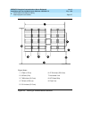
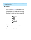
1. Place the Z113A Cable Slack Manager against the wall under the MDF.
See Figure 2-6
. Align the left side of the cable slack manager with the first
terminal block of the trunk/auxiliary field.
2. Place the next cable slack manager beside the previously installed unit.
Align the tabs and interlocks and snap the units together.
3. Repeat Step 2 until all cable slack managers are installed.
NOTE:
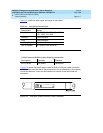
Nine 1/4-inch holes (0.63 cm) are provided in a cable slack manager
base if earthquake mounting is required. If a base is mounted on an
uneven floor, shims may be required for leveling and to assure
proper fit of the covers.
Holes are provided in the sides of the base for bolting cable slack
manager together. Bolts and shims must be obtained locally.
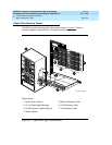
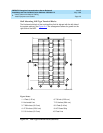
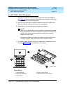
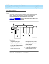
4. The system cables will route through the cable slack manager as shown.
Complete cable routing is covered later in this chapter.
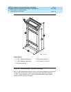
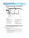
Figure 2-6. Cable Routing Through Cable Slack Manager
Figure Notes:
1. System Cabinet
2. Cable Slack Manager
3. Cable Clamp
4. Spare Center Troughs
5. Cabinet Trough for Port Cables
cbdfflr CJL 102396