


DEFINITY Enterprise Communications Server Release 6
Installation and Test for Multi-Carrier Cabinets
555-230-112
Issue 5
May 1998
Install and Wire Telephones and Other Equipment
Page 5-9DS1 Tie Trunk Example
5
DS1 Tie Trunks Using Channel Service Unit
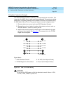
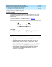
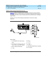
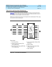
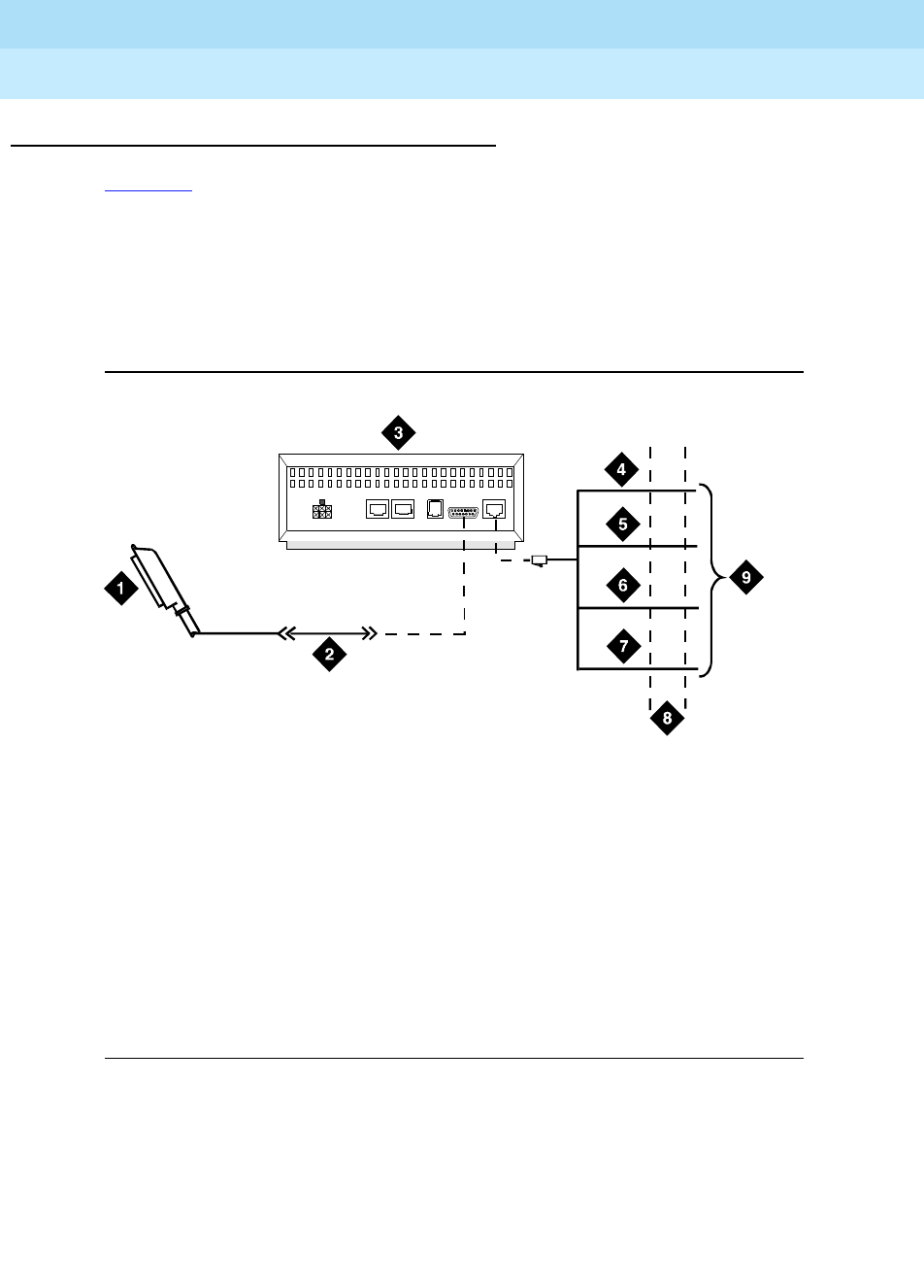
Figure 5-7 shows an example of the connections required to connect a DS1 tie
trunk to an external T1 Channel Service Unit (CSU) or Integrated Channel Service
Unit (ICSU). The ICSU is used to interface the DS1 tie trunks with the 1.544 Mbps
digital facility.
Contact your Lucent Technologies representative for maximum cabling
distances.
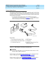
Figure 5-7. Typical Connections to Channel Service Unit
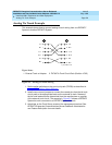
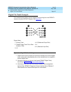
Figure Notes
1. To TN722B DS1 Tie Trunk Circuit
Pack
2. C6C Cable (For Distances Over 50
Feet (15.24 m), Use C6E Cables)
3. CSU or ICSU (3150 Shown)
4. T (Tip)
5. R (Ring)
6. T1 (Tip 1)
7. R1 (Ring 1)
8. 1.544 Mbps Digital Service Interface
9. To T1 Carrier
0012_1RBP 062696
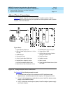
AUX PORT COM PORT MODEM
DTE
NETWO RK
POWER