


DEFINITY Enterprise Communications Server Release 6
Installation and Test for Multi-Carrier Cabinets
555-230-112
Issue 5
May 1998
Install and Wire Telephones and Other Equipment
Page 5-3
5
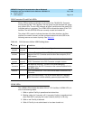
Telephone Connection Example
The 302C Attendant Console is used as an example telephone connection. This
is typical of the 603E, 84xx (4-wire), and 94xx telephones. The maximum cabling
distance for a console powered from the cabinet is 350 feet (100 meters) using
24 AWG (#5) (0.26 mm
2
) wire. The general steps to connect a telephone are:
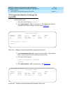
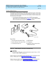
1. Choose a device to connect such as a 302C Attendant Console.
2. Choose the port circuit pack, its carrier, slot number, and port; such as
TN754B, cabinet 1, carrier C, slot 02, port 05.
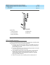
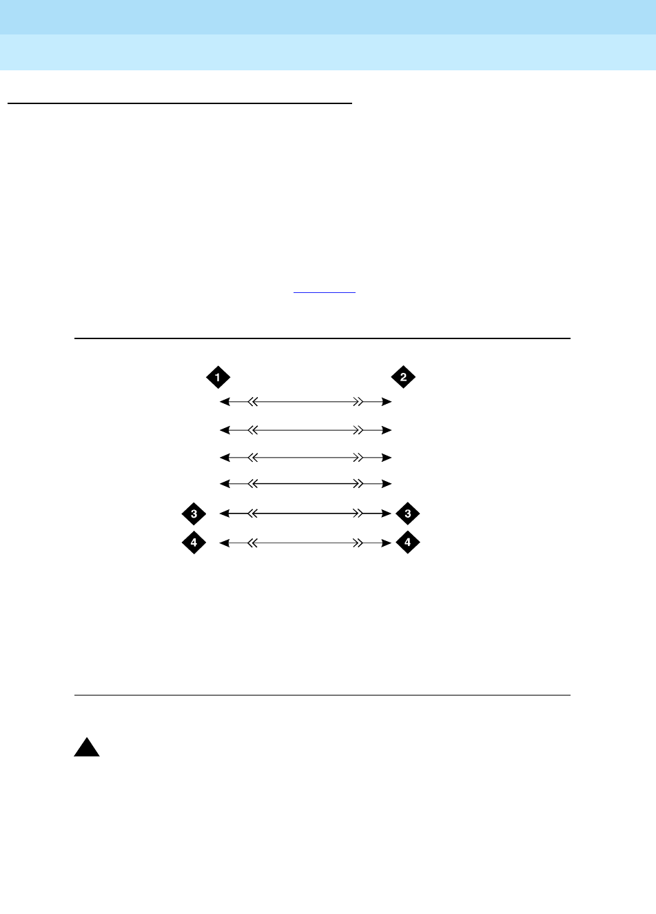
3. Install cross-connect jumpers to wire the pins on the terminal to the pins
on the port circuit pack. See Figure 5-2
. This example is for the TN754B
Digital Line circuit pack.
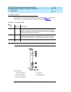
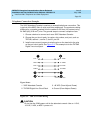
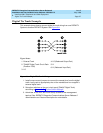
Figure 5-2. 302C to TN754B Wiring
!
CAUTION:
Do not use the 329A power unit for the attendant console. Use an 1151A,
1151A2, 1145A, or MSP-1 power unit.
Figure Notes
1. 302C Attendant Console
2. TN754B Digital Line Circuit Pack
3. -48 VDC (From Adjunct Power)
4. Ground (From Adjunct Power)
302cwireRBP 040596
1
39
14
40
15
2
3
6
7
8
TXT
TXR
PXT
PXR
TXT5
TXR5
PXT5
PXR5