


DEFINITY Enterprise Communications Server Release 6
Installation and Test for Multi-Carrier Cabinets
555-230-112
Issue 5
May 1998
Install and Wire Telephones and Other Equipment
Page 5-27TN1654 DS1 Converter (Release 6r Only)
5
Channel Service Unit Cabling
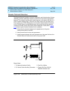
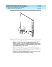
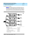
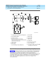
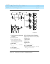
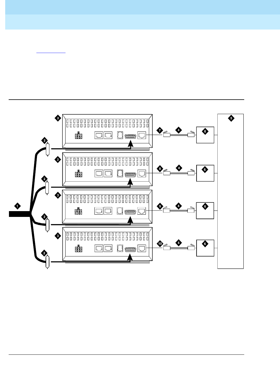
Figure 5-13 shows a typical connection from the H600-348 Quad Cable to the
CSU, through the H600-307 Network Cable, and to the network interface through
the Smart Jacks. The double-headed cable plugs into the DS1 converter slot.
The quad cable provides up to 4 DS1 connections using a 15-pin connector that
plugs into the DTE jack on each CSU. An adapter cable (comcode 107063711)
may be required to connect the H600-348 and the H600-307 cables to the CSU.
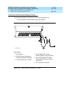
Figure 5-13. DS1 Converter Connections — Part 2
Figure Notes
1. H600-348 Quad Cable
2. 15-Pin Male “D” Connectors (to DTE Jacks
on CSU)
3. Channel Service Unit (CSU)
4. H600-307 Cable (RJ-48C to RJ-48C)
5. Network Interface
6. Smart Jack
7. Cable “A”
8. Cable “B”
9. Cable “C”
10. Cable “D”
3150csu RBP 062696
POWER
AUX P ORT COMPORT MODE M
DTE
NETWORK
POWER
AUX P ORT COMPORT MODE M
DTE
NETWORK
POWER
AUX P ORT COMPORT MODE M
DTE
NETWORK
POWER
AUX PORT COM PORT MODEM
DTE
NETWORK