


DEFINITY Enterprise Communications Server Release 6
Installation and Test for Multi-Carrier Cabinets
555-230-112
Issue 5
May 1998
Install Telecommunications Cabling
Page 2-23Cable Installation
2
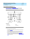
Connect Trunk Pairs to Cabinet Using Jumper
Wires To Establish 3-Pair Modularity
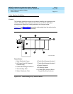
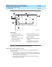
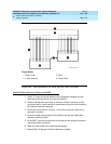
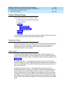
Figure 2-13 on page 2-23 and Figure 2-14 on page 2-24 show trunk pairs
connected to the cabinet with jumper wires to establish 3-pair modularity.
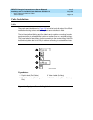
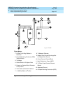
Figure 2-13. 3-Pair Modularity for Trunk Pairs for 1-Pair Trunks
To connect the trunk pairs to the purple field:
1. Connect B25A cables between the network interface and the sneak fuse
panels. See Figure 2-13
.
2. Connect A25D/B25A cables from the sneak fuse panels to the 110-type
terminal block-type connecting block connectors in the green field.
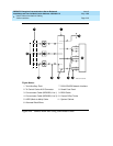
3. Connect 1-pair patch cords/jumper wires from each 110-type terminal
block row in the green field to the 110-type terminal block rows in the
purple field for 1-pair Central Office (CO) trunks or in Figure 2-14 on page
2-24 for 3-pair tie trunks.
Figure Notes:
1. Green Field
2. 1-Pair Jumpers
3. Pairs
4. Purple Field
12345678
1 4 7 10 13 16 19 22
1 4 7 1013161922
1 4 7 10 13 16 19 22
910111213141516 1718192021222324
r758425b MMR 031496