


DEFINITY Enterprise Communications Server Release 6
Installation and Test for Multi-Carrier Cabinets
555-230-112
Issue 5
May 1998
Install Telecommunications Cabling
Page 2-9Install Equipment and Cables
2
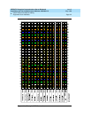
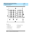
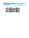
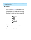
1. If you are installing 300-pair terminal blocks, draw a level horizontal line on
the wall 47.5 inches (1.2 m) above the floor. See Figure 2-3
.
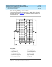
If you are installing 900-pair terminal blocks, draw a level horizontal line on
the wall 23 inches (58.4 cm) above the floor. See Figure 2-4
.
2. To mount the first trunk/auxiliary field terminal block, partially install 2
3/4-inch #12 wood screws, 7-11/16 inches (19.5 cm) apart on the left side
of the horizontal line on the wall.
3. Slide the bottom terminal block feet onto the mounting screws and mark
the upper mounting screw locations.
4. Remove the terminal block and partially install the upper mounting
screws.
5. Place the terminal block on the mounting screws and tighten the screws.
6. If installing a vertical patch cord trough, partially install the first screw for
the patch cord trough, on the line, 7/8-inch (2.2 cm) to the right of the
previous screw. Partially install the second mounting screw 5.31 inches
(13.5 cm) to the right of the screw just installed. Repeat Steps 3, 4, and 5.
7. If another trunk/auxiliary field terminal block is to be installed, partially
install the first screw for the terminal block, on the line, 7/8-inch (2.2 cm) to
the right of the previous screw. Partially install the second mounting screw
7-11/16 inches (19.5 cm) to the right of the screw just installed. Repeat
Steps 3, 4, and 5.
8. If a horizontal patch cord trough is to be installed, install it, on the line,
between the trunk/auxiliary field and the distribution field.
9. To install the first distribution field terminal block, partially install 2 3/4-inch,
#12 wood screws, 7-11/16 inches (19.5 cm) apart on the line, to the right
of the vertical patch cord trough. Repeat Steps 3, 4, and 5.
10. If installing another distribution field terminal block, partially install the first
screw for the terminal block, on the line, 7/8-inch (2.2 cm) to the right of
the previous screw. Partially install the second mounting screw 7-11/16
inches (19.5 cm) to right of the screw just installed. Repeat Steps 3, 4, and
5.
11. If installing a vertical patch cord trough in the distribution field, repeat Step
6.
12. Repeat Steps 10 and 11 until all the terminal blocks and vertical patch
cord troughs in the distribution field are installed.
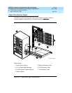
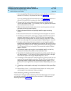
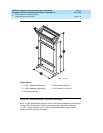
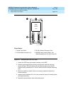
Frame Mounting 110P-Type Terminal Blocks
The 900-pair 110P-type terminal blocks and the associated patch cord troughs
can also be mounted on a free-standing, floor-mounted 1110A2 Apparatus
Mounting Frame. See Figure 2-5
.