


DEFINITY Enterprise Communications Server Release 6
Installation and Test for Multi-Carrier Cabinets
555-230-112
Issue 5
May 1998
Install and Connect Cabinets
Page 1-10Connect AC Power and Ground
1
6. At the AC load center, connect a 10 AWG (#25) (6 mm
2
) wire to the
single-point ground block. This ground wire will later be tie-wrapped to the
trunk cables and connected to the Coupled Bonding Conductor (CBC)
ground block at the MDF.
AC Load Center is More Than 50 Feet (15.2 m)
from Cabinet
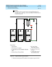
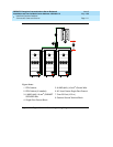
1. Mount the single-point ground block to any surface between the MCC
cabinets and the AC load center single-point ground. The single-point
ground block must be mounted to a non-metallic surface.
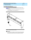
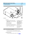
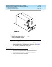
2. At the bottom rear of the PPN cabinet, connect a 6 AWG (#40) (16 mm
2
)
CABINET GROUND wire to the cabinet ground block. See Figure 1-2
.
3. Route the wire to the single-point ground block and connect.
4. At the first EPN cabinet (if provided), connect a 6 AWG (#40) (16 mm
2
)
CABINET GROUND wire to the cabinet ground terminal block.
5. Route the CABINET GROUND wire to the single-point ground block and
connect.
NOTE:
If the EPN cabinet is located remote from the PPN cabinet (in a
separate room or building), route the EPN CABINET GROUND wire
to an approved ground.
6. Repeat connecting each EPN cabinet to the single-point ground block.
7. Connect a 6 AWG (#40) (16 mm
2
) ground wire to an unused terminal on
the single-point ground block.
8. Route the ground wire to the AC load center ground and connect.