DEFINITY Enterprise Communications Server Release 6
Installation and Test for Multi-Carrier Cabinets
555-230-112
Issue 5
May 1998
Connector and Cable Diagrams
Page D-7
D
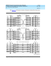
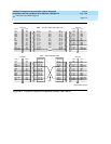
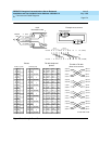
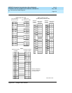
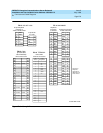
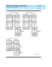
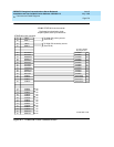
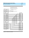
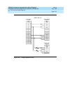
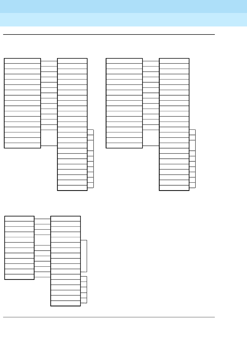
Figure D-6. Sample Cable Pinouts
1
2
15
3
4
17
5
18
6
20
8
22
24
7
21
- shield
25-pin D-sub
FS 17 H600-210 cable
37-pin D-sub
1
4
5
6
7
8
9
10
11
12
13
15
17
19
37
35
33
31
30
29
27
26
24
23
22
Strapped
wireleads
Strapped
wire leads
Strapped
wireleads
FS 19 ED1E434-11,G175
1
2
15
3
17
5
20
8
24
4
7
25-pin D-sub 37-pin D-sub
1
4
5
6
7
8
9
12
13
17
18
19
31
27
26
24
23
Resistor
1
3
15
2
4
17
5
18
6
20
8
22
24
7
21
- shield
25-pin D-sub
FS 18 H600-362 cable
37-pin D-sub
4
5
6
7
8
9
10
11
12
13
15
17
19
37
35
33
31
30
29
27
26
24
23
22
r975bb5 MMR051396


