


DEFINITY Enterprise Communications Server Release 6
Installation and Test for Multi-Carrier Cabinets
555-230-112
Issue 5
May 1998
Install Telecommunications Cabling
Page 2-14Install Sneak Fuse Panels
2
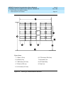
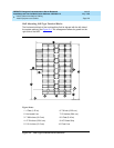
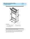
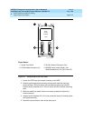
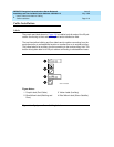
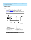
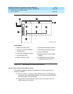
Figure 2-7. Model 507B Sneak Fuse Panel
1. Locate the 507B near the network interface or the MDF.
2. Hold the panel against the mounting surface and mark the mounting
screw locations. Drill pilot holes at the marked locations and partially
install a locally obtained #12 x 3/4-inch screw into the 2 bottom mounting
slots.
3. Slide the sneak fuse panel onto the mounting screws and tighten the
screws securely.
4. Install a locally obtained #12 x 3/4-inch screw into the top 2 mounting slots
and tighten securely.
5. Repeat the procedure for each sneak fuse panel.
Figure Notes:
1. Sneak Fuse Panel
2. 25-Pair Male Connector (In)
3. 25-Pair Female Connector (Out)
4. 220029 Fuses (Inside Panel). Use
Small Screwdriver to Pry Top Cover Off
Sneak
Current
Protector
507B
sneak CJL 032096