DEFINITY Enterprise Communications Server Release 6
Installation and Test for Multi-Carrier Cabinets
555-230-112
Issue 5
May 1998
Install Telecommunications Cabling
Page 2-15Install Sneak Fuse Panels
2
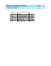
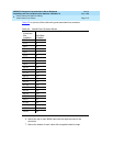
Tab le 2- 2 is a pinout of the cable wiring and associated fuse numbers.
6. Secure the top of each B25A cable with the captive screw on the
connector.
7. Secure the bottom of each cable with a supplied cable tie wrap.
Table 2-2. Sneak Fuse Connector Pinout
Connector
Pin
Numbers
Pair/Fuse
Number
26/1 1
27/2 2
28/3 3
29/4 4
30/5 5
31/6 6
32/7 7
33/8 8
34/9 9
35/10 10
36/11 11
37/12 12
38/13 13
39/14 14
40/15 15
41/16 16
42/17 17
43/18 18
44/19 19
45/20 20
46/21 21
47/22 22
48/23 23
49/34 24
50/25 25


