


DEFINITY Enterprise Communications Server Release 6
Installation and Test for Multi-Carrier Cabinets
555-230-112
Issue 5
May 1998
Install and Connect Cabinets
Page 1-19Connect DC Power and Ground
1
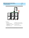
Connect DC Power and Ground
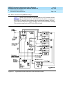
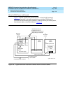
The grounding methods for the DC-powered system are more complex than that
of an AC-powered system. The following installation procedures refer to Figure
1-7. The numbers 1-8 in Figure 1-7 match the following subsections 1-8. Other
figures may be referenced as required.
!
CAUTION:
Grounding of the system shall comply with the general rules for grounding
contained in Article 250 of the National Electrical Code, NFPA 70. For more
information, refer to ‘‘
Approved Grounds’’ on page 1-23.
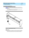
1. Install Coupled Bonding Conductor Wires
This is a conductor that connects to the single-point ground block and run
adjacent to pairs in an associated cable. The mutual coupling between the CBC
and the pairs reduces potential differences in terminating equipment. The
conductor consists of a 10 AWG (#25) (6 mm
2
) wire terminated at the CBC
ground terminal bar at the Main Distribution Frame (MDF).
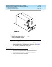
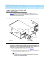
1. At the DC Power Cabinet, connect a 10 AWG (#25) (6 mm
2
) ground wire to
the Ground Discharge Bar. See Figure 1-7
.
2. Route the 10 AWG (#25) (6 mm
2
) ground wire to the CBC ground terminal
bar at the MDF. Be sure a minimum of 12 inches (30.5 cm) spacing is
maintained between the CBC and other power and ground leads.
3. Tie wrap the ground wire to the inside wiring cable.
NOTE:
The ground wires are connected to the CBC as instructed in Chapter 2,
‘‘Install Telecommunications Cabling’’.
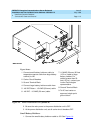
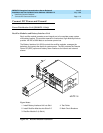
2. Connect DC Battery and Power Cabinet
Grounds
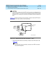
1. Measure and cut a 6 AWG (#40) (16 mm
2
) wire (comcode 846110971)
long enough to reach between the ground connection terminal in the DC
Battery Cabinet and the Ground Discharge Bar in the DC Power Cabinet.
See Figure 1-7
.
2. Crimp terminal lugs on each end of the wire. Terminal lugs are furnished
as part of D-181895, Kit of Parts (comcode 105434559).
3. At the DC Power Cabinet, connect the wire to the Ground Discharge Bar.
4. Route the wire through 1 of the holes in the side of the cabinets and
terminate it on the Ground Connection Terminal in the DC Battery Cabinet.