DEFINITY Enterprise Communications Server Release 6
Installation and Test for Multi-Carrier Cabinets
555-230-112
Issue 5
May 1998
Connector and Cable Diagrams
Page D-5
D
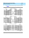
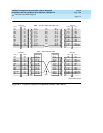
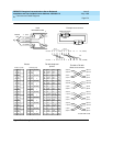
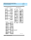
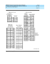
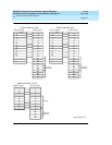
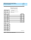
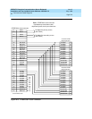
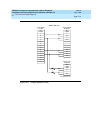
Figure D-4. Sample Cable Pinouts
FS 10 H600-348 cable
50-pinAmphenol
connectorTN1654
15-pin D-sub
DS1 interface to a CSU
Connector 01
Connector 02
Connector 03
Connector 04
23
48
22
47
20
45
19
44
17
42
16
41
14
39
13
38
LOA*
LOA
LIA
LIA*
LOB*
LOB
LIB
LIB*
LOC*
LOC
LIC
LIC*
LOD*
LOD
LID
LID*
1
9
3
11
LOA*
LOA
LIA
LIA*
1
9
3
11
LOB*
LOB
LIB
LIB*
1
9
3
11
LOC*
LOC
LIC
LIC*
1
9
3
11
LOD*
LOD
LID
LID*
FS 12
Amphenol connector
to TN1654
2
27
3
28
5
30
6
31
23
48
22
47
20
45
19
44
17
42
16
41
14
39
13
38
GRDE
XMT_DAT*
GRD
GRD
GRD
GRD
GRD
RCV_DAT*
LOA*
LOA
LIA
LIA*
LOB*
LOB
LIB
LIB*
LOC*
LOC
LIC
LIC*
LOD*
LOD
LID
LID*
FS 11 H600-347 cable
(packet gateway interface cable)
Amphenol
connector
to TN577
Amphenol
connector
toTN577
25-pin D-sub
connectors
25-pin D-sub
connectors
26
27
28
29
30
31
32
33
34
35
36
37
38
39
40
41
42
43
44
45
46
47
48
49
50
1
2
3
4
5
6
7
8
9
10
11
12
13
14
15
16
17
18
19
20
21
22
23
24
25
TC0
DCD0
RC0
CTS0
RD0
SG0
TD0
DTR0
TT0
LL0
RTS0
TC1
DCD1
RC1
CTS1
RD1
SG1
TD1
DTR1
TT1
LL1
RTS1
Connector 1
15
8
17
5
3
7
2
20
24
18
4
No connection
Connector 2
15
8
17
5
3
7
2
20
24
18
4
No connection
No connection
TC2
DCD2
RC2
CTS2
RD2
SG2
TD2
DTR2
TT2
LL2
RTS2
TC3
DCD3
RC3
CTS3
RD3
SG3
TD3
DTR3
TT3
LL3
RTS3
Connector 3
15
8
17
5
3
7
2
20
24
18
4
No connection
Connector 4
15
8
17
5
3
7
2
20
24
18
4
No connection
No connection
r975bb3 MMR 051096
Amphenol connector
toTN570 orTN573
2
31
3
28
5
30
6
27
23
48
22
47
20
45
19
44
17
42
16
41
14
39
13
38
GRDE
RCV_DAT*
GRDE
GRDE
GRDE
GRDE
GRDE
XMT_DAT*
LOA*
LOA
LIA
LIA*
LOB*
LOB
LIB
LIB*
LOC*
LOC
LIC
LIC*
LOD*
LOD
LID
LID*
Pass thru to Amphenol
connector to H600-348
or to cross connect


