


DEFINITY Enterprise Communications Server Release 6
Installation and Test for Multi-Carrier Cabinets
555-230-112
Issue 5
May 1998
Install and Connect Cabinets
Page 1-26Connect Remote Power Off Cable and External Alarm Cable
1
!
CAUTION:
The auxiliary contacts inside the EPO switch assembly must close when the
switch is pressed. This contact closure energizes the relay inside the power
distribution unit, causing the connection to the battery holdover assembly to
open.
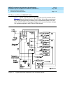
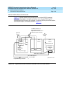
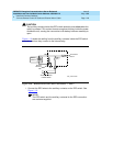
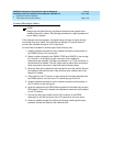
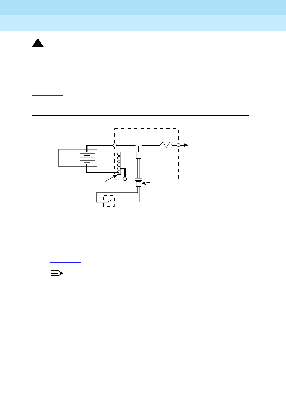
Figure 1-10 shows the cabling from the auxiliary contacts inside the EPO switch
assembly and how they connect to the internal relay.
Figure 1-10. Remote Power Off Cable Connections — Part 2
1. Connect the RPO wires to the auxiliary contacts on the EPO switch. See
Figure 1-10
.
NOTE:
The EPO switch and the auxiliary contacts for the RPO connection
are customer-supplied.
Ground
Ter minal
Bar
Shunt
RPO Cable
Power Distribution Unit
TB1
To C a r r ie r s
AtoE
TB3
Auxiliary Contacts
in EPO Switch
2
6
Battery
Cabinet
0026_3RBP 080196
Relay
(K1)