


DEFINITY Enterprise Communications Server Release 6
Installation and Test for Multi-Carrier Cabinets
555-230-112
Issue 5
May 1998
Install Telecommunications Cabling
Page 2-6Install Equipment and Cables
2
Install Equipment and Cables
Hardware Installation
The following procedures assume 1 system technician is performing the
installation. Procedures are provided for installing the following:
■ Main Distribution Frame (MDF)
■ Cable Slack Managers
■ Sneak Fuse Panels
■ Labels for the Main Distribution Frame
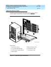
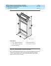
Install the Main Distribution Frame
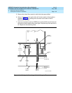
The preferred MDF location is directly behind the system cabinets.
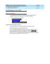
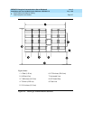
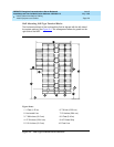
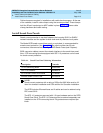
Wall Mounting 110A-Type Terminal Blocks
The 110A-type hardware can be stacked in almost any arrangement at any
height or location on the wall. One arrangement is shown in Figure 2-3
. The
distance between the mounting screw holes on the terminal blocks is 10.81
inches (27.4 cm). If a vertical patch cord trough is used, the distance between
the mounting screw holes is 5.31 inches (13.3 cm).