


DEFINITY Enterprise Communications Server Release 6
Installation and Test for Multi-Carrier Cabinets
555-230-112
Issue 5
May 1998
Install Telecommunications Cabling
Page 2-37Station Circuit Distribution from Equipment Room
2
3-Pair to 4-Pair Station Circuit Distribution
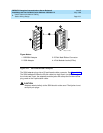
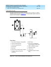
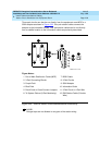
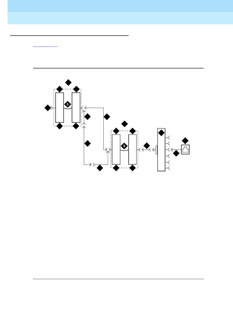
Figure 2-22 shows the 3-pair circuit distribution from an equipment room MDF to
a satellite location using 110-type hardware. Four-pair circuits are distributed
from the satellite location to the information outlets.
Figure 2-22. 3-Pair to 4-Pair Satellite Location Connectivity
Figure Notes:
1. Part of MDF
2. 3-Pair Connecting Blocks
3. Purple Field
4. White Field
5. Patch Cord or Cross-Connect
Jumpers
6. To System Cabinet (3 Pair Modularity)
7. A25D Cable (3-Pair Circuits)
8. B25A Cable
9. Connectorized (staggered finger)
Multiple 25-Pair Cable
10. 4-Pair Connecting Blocks
11. Blue Field
12. 258A or BR2580A Adapter
13. Information Outlet
14. 4-Pair Circuit [DIW Station Cable
(D-Inside Wire)]
15. Part of Satellite Location
16. 4-Pair Circuits (B25A Cable)
2
2
3
8
8
4
4
9
10
3
11
7
6
1
12
16
15
14
13