


DEFINITY Enterprise Communications Server Release 6
Installation and Test for Multi-Carrier Cabinets
555-230-112
Issue 5
May 1998
Test Telephones and Other Equipment
Page 6-7Test Stratum 3 Clock
6
Test Stratum 3 Clock
This sections tests the ability of the Stratum 3 clock to correctly provide timing
and alarms to the system.
!
CAUTION:
The following procedures are destructive to DS1 data and should not be
attempted while there are DS1 facilities in active use.
Check for Red LEDs
1. Turn on the Stratum 3 clock and wait 40-50 seconds to allow the system to
complete the on-board diagnostics before checking LEDs.
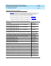
2. If there are any red LEDs, follow the procedures in Table 6-1
.
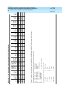
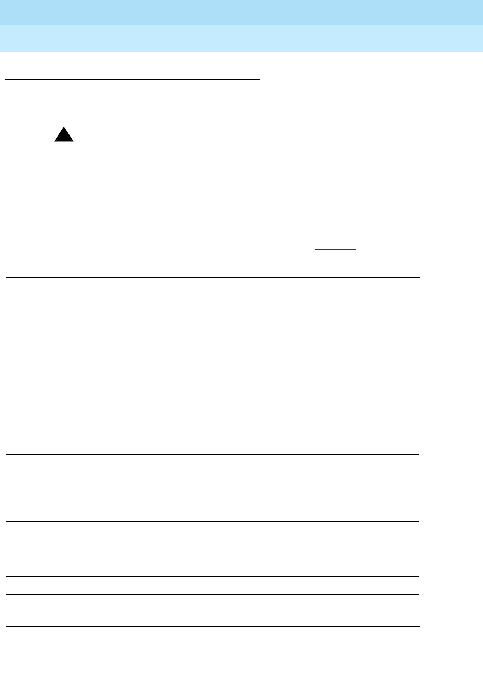
Table 6-1. Stratum 3 Clock LED Indicators
Card LED Label Procedure
PAI REF A Check that the CI circuit pack on the left is inserted properly.
Check wiring for DS1 in carrier “A” which connects the system to
the CSU and the External Synchronization Clock at the MDF
through a Y-cable assembly. If all else fails to clear the LED then
replace the circuit pack.
PAI REF B Check that the CI circuit pack on the right is inserted properly.
Check wiring for DS1 in carrier B which connects the system to
the CSU and the External Synchronization Clock at the MDF
through a Y-cable assembly. If all else fails to clear the LED then
replace the circuit pack.
PAI ST A Replace the ST3 card
PAI ST B Replace the ST3 card
CI FAIL Check wiring for its associated DS1 reference and replace the
circuit pack if necessary
ST3 FAIL Replace the circuit pack
ST3 LOCK Ignore this LED
ST3 HOLDOVER Ignore this LED
ST3 FREE RUN Ignore this LED
TOCA FAIL Replace the circuit pack
TOCA PORT ALM Replace the circuit pack if necessary