


DEFINITY Enterprise Communications Server Release 6
Installation and Test for Multi-Carrier Cabinets
555-230-112
Issue 5
May 1998
Install and Wire Telephones and Other Equipment
Page 5-41Emergency Transfer Units and Associated Telephones
5
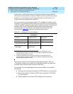
13. Check the system for transfer operation as follows:
— Place the test switch (switch 12) in the ACTIVATED position.
— The power LED should be OFF.
— Verify there is dial tone on all emergency transfer sets.
If all of the above conditions are not met, replace the panel.
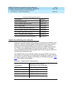
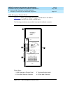
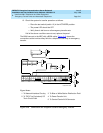
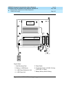
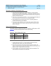
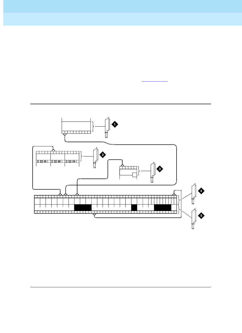
The 808A connect to the MDF with a B25A cable. Figure 5-18
shows the
connections at the trunk/auxiliary field for a telephone used only for emergency
transfer.
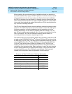
Figure 5-18. Connections for Telephone Used for Emergency Transfer
Figure Notes
1. To Network Interface Circuitry
2. To TN747 (or Equivalent) CO
Trunk Circ uit Pac k
3. To Blue or White Station Distribution Field
4. To Power Transfer Unit
5. To Control Carrier AUX Connector
TC TK LC ST
1M 1m 2M 2m 3M
ALARM MONITORS EM TRANS RELAY PWR ACC PWR
3m 3w
TC TK LC ST TC TK LC ST TC TK LC ST TC TK LC ST
C
O
M
1
N
O
1
N
C
2
N
C
1
C
O
M
2
N
O
2
C
O
M
3
N
C
3
G
R
D
-48
V
123
2822
25
50
1
EMXR
2822
r758580b MMR 042996