


DEFINITY Enterprise Communications Server Release 6
Installation and Test for Multi-Carrier Cabinets
555-230-112
Issue 5
May 1998
Install Telecommunications Cabling
Page 2-21Cable Installation
2
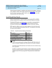
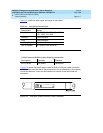
Connect Control Carrier Outputs Cable
Plug the connector cable in the AUX connector on the rear of the Control Carrier.
Route the connector cable through the cable slack manager to the assigned
110-type terminal block in the yellow field of the trunk/auxiliary field.
Install Trunk Cables Among Network Interface,
Sneak Fuse Panel, and Cabinet
The 1-pair of Central Office (CO) trunks are installed by the network provider in
the green field. Up to 24 pairs may be terminated on each row of the 110-type
terminal block. Tie trunks also appear in the green field with up to eight 3-pair
trunks terminated on each row of the 110-type terminal block.
Select Concentrator Cables
WP-90929, List 1 and 3 concentrator cables can be used to connect the cabinet
to the 110-type terminal blocks in the purple field. The 1-pair patch cords/jumper
wires are then run from the purple terminal block rows to the green terminal block
rows in order to establish the correct 3-pair modularity.
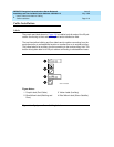
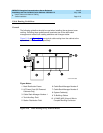
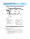
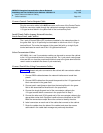
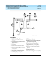
Connect Trunk Pairs Using Concentrator Cables
Figure 2-12 shows trunk pairs connected to the cabinet with concentrator cables.
To install the cables:
1. Connect B25A cables between the network interface and sneak fuse
panels.
2. Connect A25D cables from the sneak fuse panels to the 110-type terminal
block connectors in the green field.
3. Connect patch cords/jumper wires from the terminal block in the green
field to the associated terminal block in the purple field.
4. Connect the single-fingered end of the concentrator cables to the
110-type terminal block connectors in the purple field in Step 3.
5. Connect the other end (2/3-fingered end) of the concentrator cables to the
appropriate carrier slots. Equipped carrier slots are identified on the CSD.
Mark the nomenclature strips above the carriers to identify the slots.
6. Label connectors on each end of the cables that connect to the cabinet.
7. Route the cables down the sides of the cabinet and store the excess
cable slack in the cable slack manager as previously described.