


DEFINITY Enterprise Communications Server Release 6
Installation and Test for Multi-Carrier Cabinets
555-230-112
Issue 5
May 1998
Install and Wire Telephones and Other Equipment
Page 5-5Analog Station or 2-Wire Digital Station Example
5
Analog Station or 2-Wire Digital
Station Example
This example is typical of the 2-wire digital stations (603E, 84xx, 94xx, 302C),
2-wire analog stations (500, 2500, 71xx), analog CO trunks, DID trunks, and
external alarms.
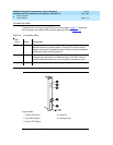
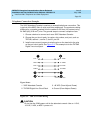
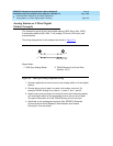
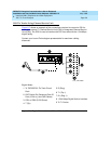
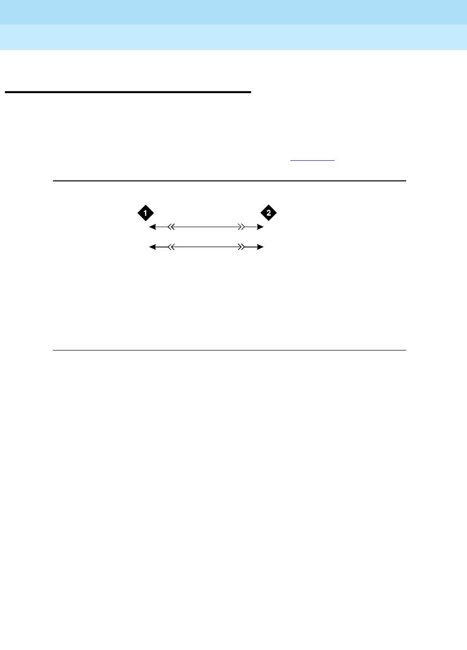
The wiring designations for this example are shown in Figure 5-4
.
Figure 5-4. 2500-Type Analog Telephone Wiring
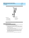
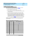
1. Choose a peripheral to connect (such as an analog station or 2-wire digital
station).
2. Choose the port circuit pack, its carrier, slot number, and port. For
example TN2183 Analog Line, cabinet 1, carrier C, slot 1, port 03.
3. Install cross-connect jumpers to connect the pins from the analog station
or 2-wire digital station to the appropriate pins on the port circuit pack.
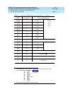
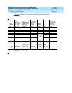
This pinout information is for the TN2183 Analog Line circuit pack.
4. Administer on the management terminal. See
DEFINITY Enterprise
Communications Server Release 6 Administration and Feature
Description
, for more details.
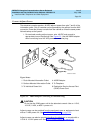
Figure Notes
1. 2500-Type Analog Station 2. TN2183 Analog Line Circuit Pack
(Position 1C01)
2500wire RBP 071996
3
28
03
2T
R
T.3
R.3