


DEFINITY Enterprise Communications Server Release 6
Installation and Test for Multi-Carrier Cabinets
555-230-112
Issue 5
May 1998
Install and Connect Cabinets
Page 1-34Earthquake Protection Installation
1
Earthquake Protection Installation
Install Concrete Floor Mounting
1. Position the cabinet in the exact position it is to occupy when the
installation is complete.
2. Insert a pencil or marker through the holes previously occupied by the
carriage bolts (front and rear) in the bottom of the cabinet and mark the
floor directly beneath each hole.
3. Roll the cabinet out of the way and drill four 1/2-inch (1.27 cm) diameter
holes about 1.5 inches (3.8 cm) deep at the locations marked in Step 2.
4. Insert concrete floor anchors (STARR part number 3425) into the holes.
5. Roll the cabinet back into place and align the cabinet holes over the
concrete floor anchors.
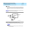
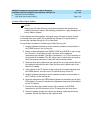
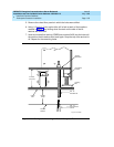
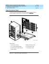
6. Adjust the leveling legs until the cabinet is level. See Figure 1-14
.
NOTE:
If the system is supplied with cable ductwork, the cabinets must be
level from front to rear and from side to side. They must be square
with respect to each other to within ±1/8-inch (0.3 cm).
7. Secure the cabinet to the floor with the 4 supplied 3/8-16 x 4.5-inch (11.4
cm) bolts and four 3/8-inch flat washers.
8. Repeat this procedure for each cabinet to be installed.
Install Raised Computer Floor Mounting
1. Position the cabinet in the exact position it is to occupy when the
installation is complete.
2. Insert a pencil or marker through the holes previously occupied by the
carriage bolts (front and rear) in the bottom of the cabinets and mark the
raised floor panels directly beneath each hole.
3. Roll the cabinet out of the way and drill 4 holes 5/8-inch (1.6 cm) in
diameter through the raised floor panels marked in Step 2.
!
CAUTION:
Take care while drilling the holes through the raised floor that the drill
bit does not penetrate any cables below the floor that could cause
damage to the cable or injury to the installer.
4. Insert a long punch through the holes drilled in Step 3 and mark the
concrete floor beneath the raised floor panels.