


DEFINITY Enterprise Communications Server Release 6
Installation and Test for Multi-Carrier Cabinets
555-230-112
Issue 5
May 1998
Test the System
Page 4-14LED Indicators
4
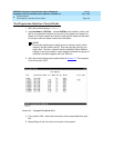
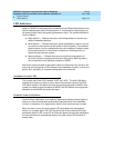
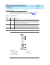
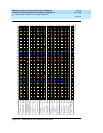
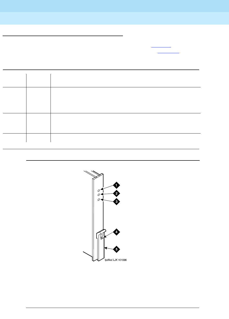
Circuit Pack LEDs
Typically, each circuit pack has 3 LEDs on the front panel. Tab le 4- 1 describes
the red, green, and yellow LEDs and their meaning. Also see Figure 4-1
.
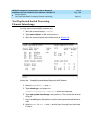
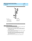
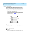
Figure 4-1. Circuit Pack LEDs
Table 4-1. Circuit Pack LEDs
LED
Color Status Description
Red Alarm The system has detected a fault in this circuit pack. The alarm log
should contain an on-board alarm. The red LED is also lit briefly
when a circuit pack is inserted or reset. If the circuit pack passes its
initialization tests, the LED goes out.
Green Testing The system is currently running tests on this circuit pack as part of
background maintenance or demand testing. This LED is also lit
during initialization tests when a circuit pack is inserted or reset.
Yellow Busy The circuit pack is currently in use by the system.
Figure Notes
1. Alarm LED (Red)
2. Test LED (Green)
3. Busy LED (Yellow)
4. Latch Pin
5. Locking Lever