


DEFINITY Enterprise Communications Server Release 6
Installation and Test for Multi-Carrier Cabinets
555-230-112
Issue 5
May 1998
Install and Wire Telephones and Other Equipment
Page 5-11Auxiliary Connector Outputs
5
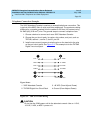
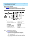
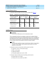
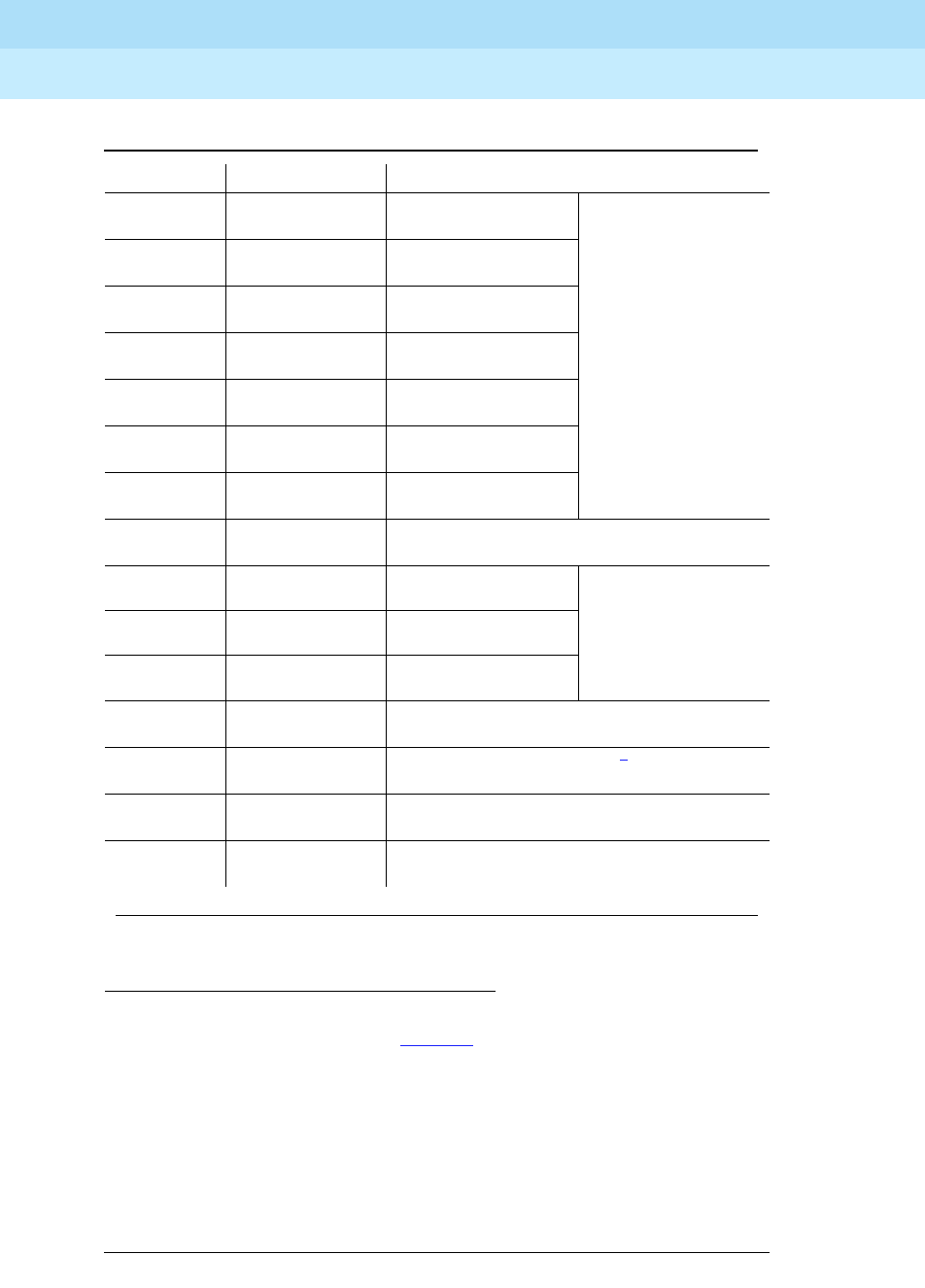
1. Color designation is the main wire color followed by the color of the stripe.
2. The following wire colors apply in Table 5-2
:
WWhite
BL Blue
O Orange
GGreen
BR Brown
S Slate (Grey)
RRed
BK Black
YYellow
V Violet
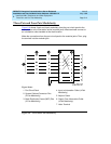
3. External alarm with signal incoming to system.
BK-BL
BL-BK
36
11
-48
GND
Emergency
Transfer
Relay
Power
↓
BK-O
O-BK
37
12
-48
GND
BK-G
G-BK
38
13
-48
GND
BK-BR
BR-BK
39
14
-48
GND
BK-S
S-BK
40
15
-48
GND
Y-BL
BL-Y
41
16
-48
GND
Y-O
O-Y
42
17
-48
GND
Y-G
G-Y
43
18
Not Connected
Y-BR
BR-Y
44
19
GND
-48
AUX Power
Y-S
S-Y
45
20
GND
-48
V-BL
BL-V
46
21
GND
-48
V-O
O-V
47
22
Not Connected
V-G
G-V
48
23
Ext Alarm A
3
Ext Alarm Return
V-BR
BR-V
49
24
Not Connected
V-S
S-V
50
25
INADS Tip
INADS Ring
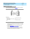
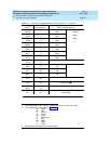
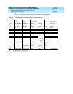
Table 5-2. Auxiliary Lead Appearances at AUX Connector — Continued
Color
1,2
Pin Number AUX Connector Outputs
Continued on next page