


DEFINITY Enterprise Communications Server Release 6
Installation and Test for Multi-Carrier Cabinets
555-230-112
Issue 5
May 1998
Install Management Terminal and Activate System
Page 3-25Administer Fiber Links (Release 6r Only)
3
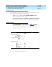
10. In the Line Coding: field, enter the line coding information. This
information should match the line coding of the facility. For T1, example
line coding is b8zs. For E1, example line coding is hdb3.
NOTE:
If this data is not correct, wideband errors (multimedia call handling)
may occur.
11. For T1 sites, refer to ‘‘
T1 Installations Only’’. For E1 sites, refer to ‘‘E1
Installations Only’’.
T1 Installations Only
a. The Framing Mode: field is display only and shows the hardware setting.
b. The DS1CONV-1 Line Compensation: and the DS1CONV-2 Line
Compensation: fields are display only and show the hardware setting.
c. In the Facility A Circuit ID: field, enter an optional facility name
that is unique to each facility (up to 40 alphanumeric characters). Press
Enter.
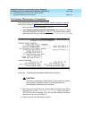
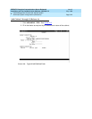
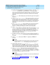
d. A display similar to the following appears after the fiber link administration
is completed:
RESET PORT-NETWORK 2 LEVEL 2 (COLD) PERFORMED.
E1 Installations Only
a. Enter y or n in the CRC? field. The “CRC” means Cyclic Redundancy
Check. This is an error detection algorithm.
b. The Line Termination: field is display only. A 75 (75 Ohms) or 120
(120 Ohms) typically displays.
c. In the Facility A Circuit ID: field, enter an optional facility name
that is unique to each facility (up to 40 alphanumeric characters). Press
Enter.
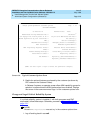
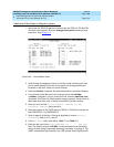
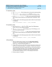
d. A display similar to the following appears after the fiber link administration
is completed:
RESET PORT-NETWORK 2 LEVEL 2 (COLD) PERFORMED.