


DEFINITY Enterprise Communications Server Release 6
Installation and Test for Multi-Carrier Cabinets
555-230-112
Issue 5
May 1998
Install Telecommunications Cabling
Page 2-39Layout
2
Layout
Locate Information Outlets
The customer or marketing representative must provide floor plans showing the
information outlet locations and types (flush- or surface-mounted) required. The
floor plans must also show a complete overview of all conduit and cabling
facilities in the building.
Locate Satellites and Sites
Use the following information when determining site, satellite, or adapter
locations.
a. Keep the number of locations to a minimum.
b. To minimize the station wiring distances, centrally locate the
sites/satellites, or adapters among the information outlets.
c. Site/satellite locations must be easily accessible and contain AC-powered
receptacles.
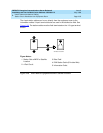
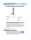
Adapter Requirements
One 258A/BR2580A adapter is required for each 25-pair station cable containing
4-pair station circuits. One 356A adapter is required for each 25-pair station
cable containing 3-pair station circuits.
Hardware Requirements
Hardware requirements are the same as for the equipment room.
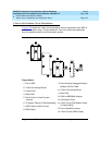
Sizing 4-Pair Station Cables
Use the scale of the floor plan to determine the approximate length of the station
cables required per the standard SYSTIMAX wiring concepts.
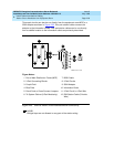
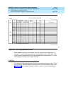
Sizing 25-Pair and Multiple 25-Pair Station
Cables
Use the scale of the floor plan to determine the approximate length of each
25-pair station cable. The cables must be selected and properly sized to make
maximum use of the hardware at the equipment room or satellite location.
Use 25-pair B25A cables to connect adapters directly to the MDF or satellite
location. Staggered-finger cables, equipped with factory-installed 25-pair
connectors at both ends, should be used when multiple 25-pair cables are used