


DEFINITY Enterprise Communications Server Release 6
Installation and Test for Multi-Carrier Cabinets
555-230-112
Issue 5
May 1998
Install Telecommunications Cabling
Page 2-28Station Wiring Design
2
Station Wiring Design
The following hardware and cabling is used:
■ Information outlets (modular wall jacks)
■ Station Cables
■ Closets
— Site locations
— Satellite locations
■ Adapters
■ Labels
A brief description of each of the above listed items follows. Ordering information
is not provided for station cables and information outlets.
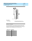
Information Outlets
Information outlets are 8-pin modular wall jacks. Most of the outlets are wired with
push-on connections. Information outlets are also available that connect to a
double modular plug-ended 4-pair station cable routed from the MDF, a
site/satellite location, or an adapter.
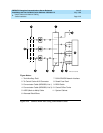
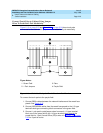
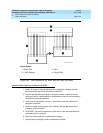
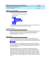
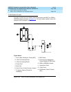
Station Cables
For clarity, a station cable is either a 25-pair cable, multiple 25-pair cable, or
4-pair D-inside wire (DIW) run from the equipment room, site/satellite location, or
adapter to the information outlets. The following station cables are available. See
Figure 2-16
.
25-pair station cable
— Use between the equipment room and site/ satellite
locations or adapters. Use an A25D cable (male to male) between the equipment
room and satellite closet. Use a B25A cable between the equipment room and
site closet or adapter.
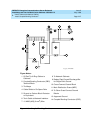
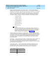
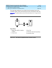
Multiple 25-pair station cable
— Use between the equipment room and
site/satellite locations or adapters. This cable consists of individually sheathed
25-pair cables with a factory-installed 25-pair connector on each end. Use a
male to female cable to connect between the equipment room and site location
or adapter. Use a male to male cable to connect between the equipment room
and satellite location. Staggered-finger cables are recommended for all multiple
25-pair station cables and are available in both double-ended and single-ended
types.