


DEFINITY Enterprise Communications Server Release 6
Installation and Test for Multi-Carrier Cabinets
555-230-112
Issue 5
May 1998
Install Telecommunications Cabling
Page 2-25Cable Installation
2
Install Connector Cables Between Auxiliary
Cabinet and MDF
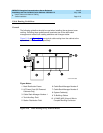
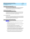
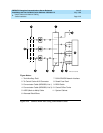
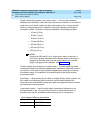
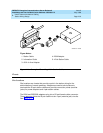
Auxiliary equipment that connects to the MDF can be mounted inside the
Auxiliary cabinet. The equipment connects to an ED-1E1443-10 (Group 1)
intraconnection panel mounted in the cabinet. This intraconnection panel
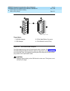
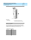
consists of a 110-type 100-pair wiring block. Auxiliary equipment is connected to
the 110-type wiring block. The wiring block is pre-wired to four 25-pair female
connectors mounted on the outside rear of the cabinet.
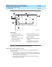
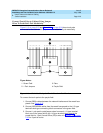
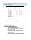
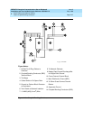
1. Install “D” rings on the wall between the cable slack manager and the
terminal/connecting blocks mounted on the MDF.
2. Install a self-sticking port label on the rear of each connector on the B25A
connector cable. See Figure 2-9 on page 2-17
.
NOTE:
Labels should be positioned so they will not be obscured by the
cabinet connector retainers.
3. At the rear of the Auxiliary cabinet, connect 1 end of the connector cable
to the assigned connector.
4. Route the cable down the rear of the cabinet and through the cable slack
manager to the MDF.
5. At the MDF, connect the other end of the cable to the assigned
terminal/connecting block connector.
6. Store the excess cable in the cable slack manager.
7. Repeat Steps 2 through 6 until all cables are installed.