


DEFINITY Enterprise Communications Server Release 6
Installation and Test for Multi-Carrier Cabinets
555-230-112
Issue 5
May 1998
Install and Wire Telephones and Other Equipment
Page 5-60BRI Terminating Resistor
5
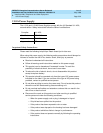
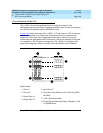
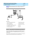
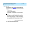
Figure 5-25 shows the wiring connections for the 110RA1-12 terminal block. The
TN556 Basic Rate Interface (BRI) switch port is terminated to bottom row C.
Figure 5-25. Typical Installation of Terminating Resistor Block (110RA1-12)
For point-to-point wiring, the top row connects to the blue station field. The pair
connects from the 110RA1-12 to the standard 4-pair circuit. Pair 1 from the
110RA1-12 connects to Pair 1 of the station field, and Pair 2 connects to Pair 3 of
the station field.
Two terminal basic multipoint applications are accommodated by connecting row
B (output) to the second terminal common to the multipoint circuit.
Figure Notes
1. Part of Terminating Resistor Block
2. White or Purple Field
3. Part of 4-Pair Blue Field
4. From ISDN T-interface Circuit (2-Pair)
5. To ISDN S/T-interface terminals
6. 2-Pair Cross-Connect
7. Basic Multi-point Option
8. 2-Pair Cross-Connect
9. 4-Pair Horizontal Cables
10. Row “A”
11. Row “B”
12. Row “C”
TT1RR1
10
3
4
5
1
6
2
8
12
9
11
7