


DEFINITY Enterprise Communications Server Release 6
Installation and Test for Multi-Carrier Cabinets
555-230-112
Issue 5
May 1998
Install and Wire Telephones and Other Equipment
Page 5-38Emergency Transfer Units and Associated Telephones
5
NOTE:
Install the 808A in a location that can be accessed only by authorized
personnel. In addition, the location must meet standard environmental
considerations such as temperature, humidity, and so forth.
6. Install the panel on any mounting frame in either a vertical or horizontal
position. The housing has ears for screw-mounting and cutouts for
snap-mounting the unit in an 89-type mounting bracket. Verify dial tone is
present at each trunk circuit.
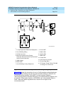
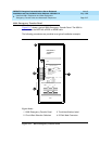
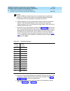
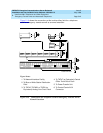
7. Locate the circuit start selection switches. See Figure 5-17
. These are the
first 10 two-position switches on the left side of the panel. They are used to
set each of the 5 incoming trunk lines to either loop start or ground start.
Two switches are used for each circuit; switches 1 and 2 are used for
circuit 1, switches 3 and 4 are used for circuit 2, and so forth. See Ta b le
5-13. For loop start, set the switches to the left. For ground start, set the
switches to the right.
.
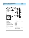
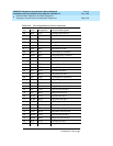
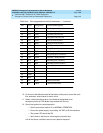
8. Connect a 25-pair cable between the male RJ21 25-pair connector on the
Emergency Transfer Panel and the yellow field of the MDF. See Figure
5-18. Table 5-14 shows the pin assignments.
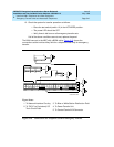
9. Make cross-connections for each emergency trunk/emergency station
pair. See Figure 5-19
and Table 5-14.
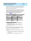
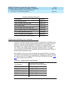
Table 5-13. Trunk/Test Switches
Switch
Number
Circuit
Number
11
21
32
42
53
63
74
84
95
10 5
11 Not Used
12 Test Switch