


DEFINITY Enterprise Communications Server Release 6
Installation and Test for Multi-Carrier Cabinets
555-230-112
Issue 5
May 1998
Install and Wire Telephones and Other Equipment
Page 5-23TN1654 DS1 Converter (Release 6r Only)
5
TN1654 DS1 Converter (Release 6r
Only)
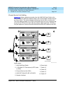
Set Circuit Pack Switches
The configuration switches on the TN1654 must be set before the circuit pack is
installed. The TN1654 can be configured for either T1 or E1 operation. All 4
facilities on the circuit pack are configured as a group. It is not possible to have
T1 and E1 facilities supported on the same circuit pack at the same time.
E1 facility line termination impedances of 120 Ohms for twisted-pair and 75
Ohms for coax wiring are supported. The T1 line impedance is fixed at 100 Ohms
and the T1 framing is selectable for ESF (Extended Super Frame) or D4 for each
facility.
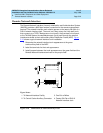
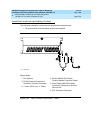
Figure 5-11
shows the location of the switches. Table 5-9 shows the switch
setting positions and functions.
1. Set the configuration switches on the TN1654 as required per site.
2. Set Switch 6 down (disabled).
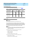
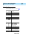
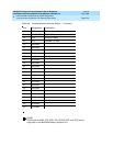
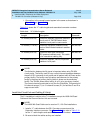
Table 5-9. TN1654 DS1 Converter Configuration Switches
Switch Function Up Down
1 Type of Facility T1 E1
2 Span A Line Impedance (E1 Only)
Span A Framing (T1 Only)
120 Ohm
ESF
75 Ohm
D4
3 Span B Line Impedance (E1 Only)
Span B Framing (T1 Only)
120 Ohm
ESF
75 Ohm
D4
4 Span C Line Impedance (E1 Only)
Span C Framing (T1 Only)
120 Ohm
ESF
75 Ohm
D4
5 Span D Line Impedance (E1 Only)
Span D Framing (T1 Only)
120 Ohm
ESF
75 Ohm
D4
6 Force Fiber Data-Stream
Scrambling
Enabled Disabled