


DEFINITY Enterprise Communications Server Release 6
Installation and Test for Multi-Carrier Cabinets
555-230-112
Issue 5
May 1998
Cable Ductwork
Page C-9
C
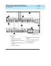
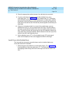
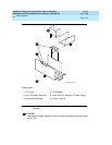
8. Route the appropriate cables between the cabinets just connected.
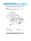
9. If a given cabinet is to support a cross-aisle shielded duct, set a
cross-aisle riser (“C” in Figure C-4
) on the cabinet riser (“A”). Otherwise
set a shielded coupling (“D”) on the cabinet riser. In either case, position
the device so the two holes on the back wall line up with the holes on the
back wall of the cabinet riser. Bolt the two pieces together at the holes just
described.
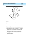
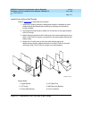
10. If there is no trough to install in one end of the cabinet riser, press a
shielded end cap (“E”) on the unused end of the riser. The side walls of
the end cap go inside the walls of the riser and outside of the ears of the
riser. The top of the end cap should rest on top of the shielded coupling or
cross-aisle riser previously installed. Bolt the bottom of the end cap to the
cabinet riser with a self-tapping screw.
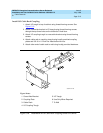
11. Set the shielded cover (“D”) on the shielded trough (“B”) and press it
down so the dimples on the cover engage the holes in the trough.
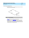
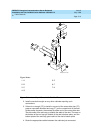
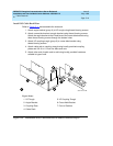
Install Cross-Aisle Shielded Ducts
The inter-cabinet ducts and cross-aisle risers must be installed before any
cross-aisle ductwork is installed.
1. Set the tongue on the bottom of a cross-aisle trough (“G” in Figure C-5
)
into the platform of the cross-aisle riser (“C”). From above the trough, run a
self-tapping screw through the slot in the trough and into the hole in the
riser.