DEFINITY Enterprise Communications Server Release 6
Installation and Test for Multi-Carrier Cabinets
555-230-112
Issue 5
May 1998
Connecting Fiber Optic Cables
Page A-6Optical Cross-Connect Hardware
A
Optical Cross-Connect Hardware
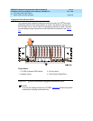
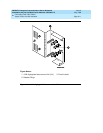
Optical cross-connects consist of a preterminated lightguide shelf or Lightguide
Interconnect Unit (LIU) with lightguide troughs. A multi-mode or single-mode
fiber optic cable connects the lightwave transceivers on the DEFINITY System to
connector panels inside the shelf or LIU. Circuits can be changed by moving the
patch cord from 1 point on the connector panel to another.
Measuring Single-Mode Power in the Field
The data pattern on the link influences the optical power measurement. The duty
cycle that the transceiver is sending when the DEFINITY System is idle is a 30%
on (“1”) and 70% off (“0”) data pattern. This implies that the optical reading will
be about 2.3dB less than the typical output power specification (-8dBm).
Calculate all power budget analysis at 50% duty cycle for both transmitter output
power and receiver sensitivity.
The following information is provided for field troubleshooting use only and is not
intended for fiber budget analysis.
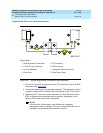
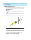
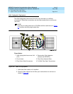
The power measurement is taken from the TX connector, through the entire fiber
link, and to the RX connector on the opposite end of the link (remote EPN). Refer
to Figure A-2
for a typical fiber route.
1. Remove the fiber cable from the RX connector at the local 300A.
2. Attach the power meter to the fiber cable. Note the reading.
3. Reconnect the RX cable.
4. Repeat the test at the RX connector at the remote 300A. Note the reading.
5. Reconnect the RX cable.
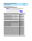
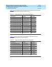
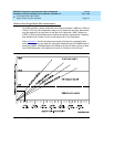
6. Using Figure A-1
, determine the type of in-line attenuator required for each
direction in the tested fiber link.
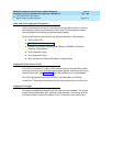
NOTE:
Using the maximum power budget of 17dB in any fiber link may
cause problems if the fiber plant is damaged and additional
connectors or splices are added. Maintain a margin of at least 1dB;
2dB is the industry standard.


