


DEFINITY Enterprise Communications Server Release 6
Installation and Test for Multi-Carrier Cabinets
555-230-112
Issue 5
May 1998
Install Telecommunications Cabling
Page 2-24Cable Installation
2
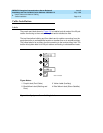
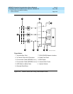
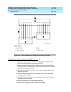
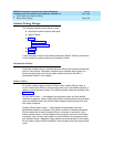
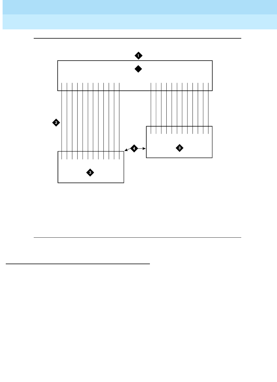
Figure 2-14. 3-Pair Modularity for Trunk Pairs for 3-Pair Tie Trunks
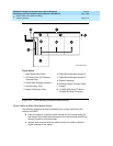
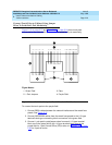
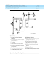
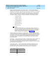
Install Cables Between Cabinet and MDF
1. Install “D” rings on the wall between the cable slack manager and the
terminal/connecting blocks mounted on the MDF.
2. Install a self-adhesive port label on the back of each connector on the
connector cable. Labels should be positioned so they are not covered by
the cabinet connector retainers.
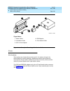
3. At the rear of the cabinet, connect 1 end of the connector cable to the
assigned connector.
4. Route the cable down the rear of the cabinet, through the cable slack
manager, and to the MDF.
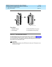
5. At the MDF, connect the other end of the cable to the assigned terminal/
connecting block connector.
6. Store the cable slack in the cable slack manager.
7. Repeat Steps 2 through 6 until all cables are installed.
Figure Notes:
1. Green Field
2. 1-Pair Jumpers
3. Pairs
4. Purple Field
123456789101112
123456789101112
123456789101112
1716151413 18 19 20 21 22 23 24
3
r758537bMMR 031496