


DEFINITY Enterprise Communications Server Release 6
Installation and Test for Multi-Carrier Cabinets
555-230-112
Issue 5
May 1998
Install and Wire Telephones and Other Equipment
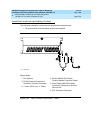
Page 5-21Connect Power Distribution Unit External Alarm Wires
5
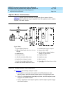
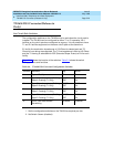
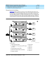
1. Choose an alarm to connect (such as Battery Interface Failure).
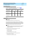
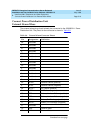
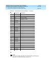
2. Choose the port circuit pack to use and its carrier and slot number (from
Tab le 5- 3
). For example TN2183 Analog Line, Cabinet 1, Carrier C, Slot 1.
3. Choose a port circuit on the port circuit pack, for example Port 3.
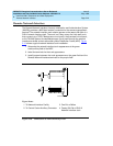
4. Install cross-connect jumpers to connect the named pins from the alarm
wires to the appropriate pins on the port circuit pack.
NOTE:
It is recommended that the RFA, ACF, and BIF alarm leads be
connected to the major alarm device and the BOD alarm leads be
connected to the minor alarm device.
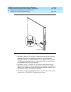
5. Connect the major and minor alarm devices to the appropriate cross-
connect pins on the MDF.
6. Administer the alarms using
DEFINITY Enterprise Communications Server
Release 6 Administration and Feature Description
.