


DEFINITY Enterprise Communications Server Release 6
Installation and Test for Multi-Carrier Cabinets
555-230-112
Issue 5
May 1998
Install and Wire Telephones and Other Equipment
Page 5-13Three-Pair and Four-Pair Modularity
5
Three-Pair and Four-Pair Modularity
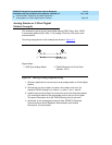
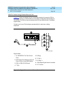
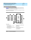
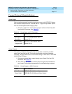
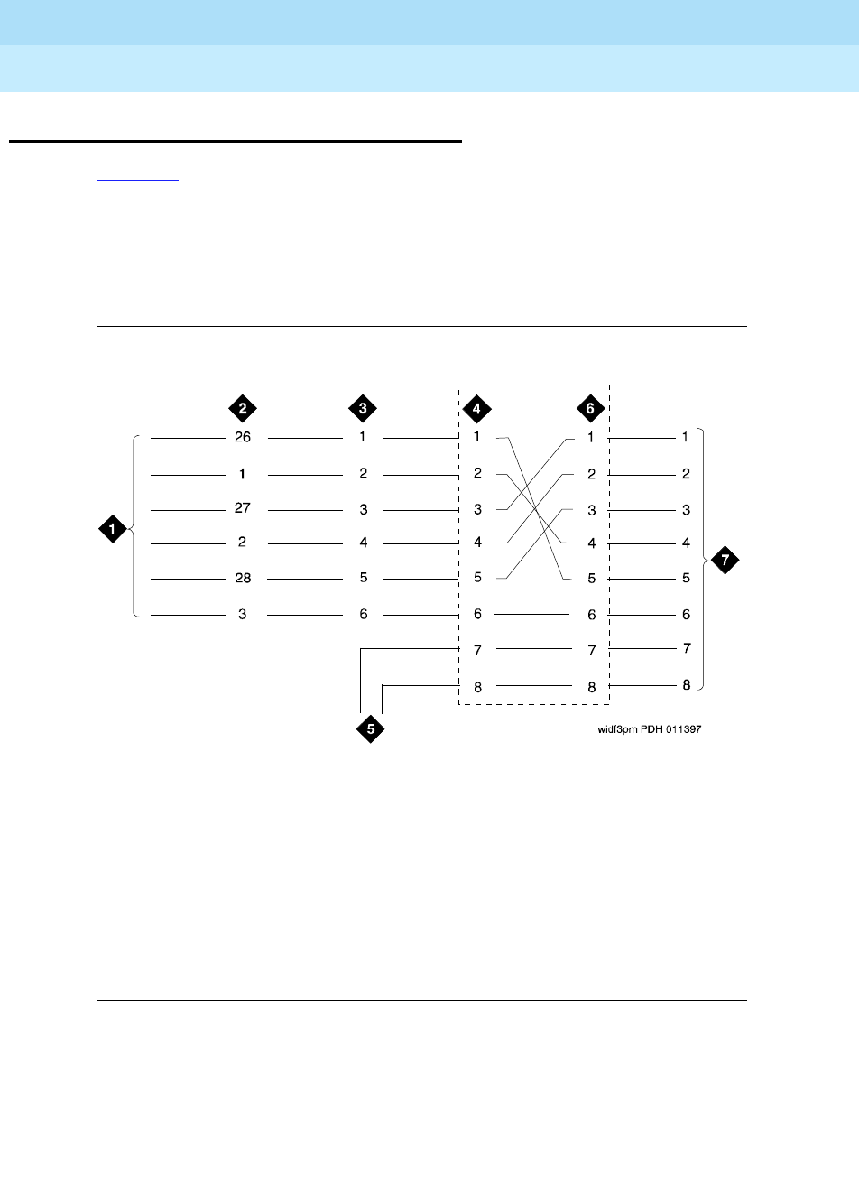
Figure 5-8 shows 3-pair and 4-pair modularity from the port circuit pack to the
terminal pins at the information outlet (modular jack). Most terminals connect to
an information outlet installed at the work location.
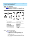
Make the connections from the port circuit pack to the modular jacks. Then, plug
the terminal into the modular jack.
Figure 5-8. 3-Pair and 4-Pair Modularity
Figure Notes
1. Port Circuit Pack
2. System Cabinet Connector Pins
(3-Pair Modularity)
3. Main Distribution Frame (MDF) Pins
(3-Pair Modularity)
4. Input to Information Outlet (4-Pair
Modularity)
5. Adjunct Power
6. Output From Information Outlet
(4-Pair Modularity)
7. Voice Terminal