


DEFINITY Enterprise Communications Server Release 6
Installation and Test for Multi-Carrier Cabinets
555-230-112
Issue 5
May 1998
Install and Wire Telephones and Other Equipment
Page 5-22Remote Network Interface
5
Remote Network Interface
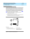
The Remote Network Interface (formerly Initialization and Administration System
(INADS)) provides a 9600 bps modem connection for the remote management
terminal. The network interface trunk should appear on the twenty-fifth pair of a
RJ21X network interface jack. The trunk is a 2-way, rotary dial, loop start trunk
that connects to a TN731 Maintenance circuit pack, the processor circuit pack,
or the TN1648 System Access/Maintenance circuit pack through the network
interface terminals at the trunk/auxiliary Main Distribution Frame (MDF). Figure
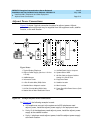
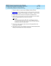
5-10 shows a typical network interface trunk installation.
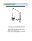
1. Determine the network interface trunk appearance at the green
trunk/auxiliary field of the MDF.
2. Label the terminals for the trunk appearance.
3. Install jumpers between the trunk appearance on the green field and the
Remote Network Interface terminals on the purple field.
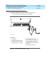
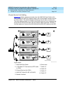
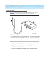
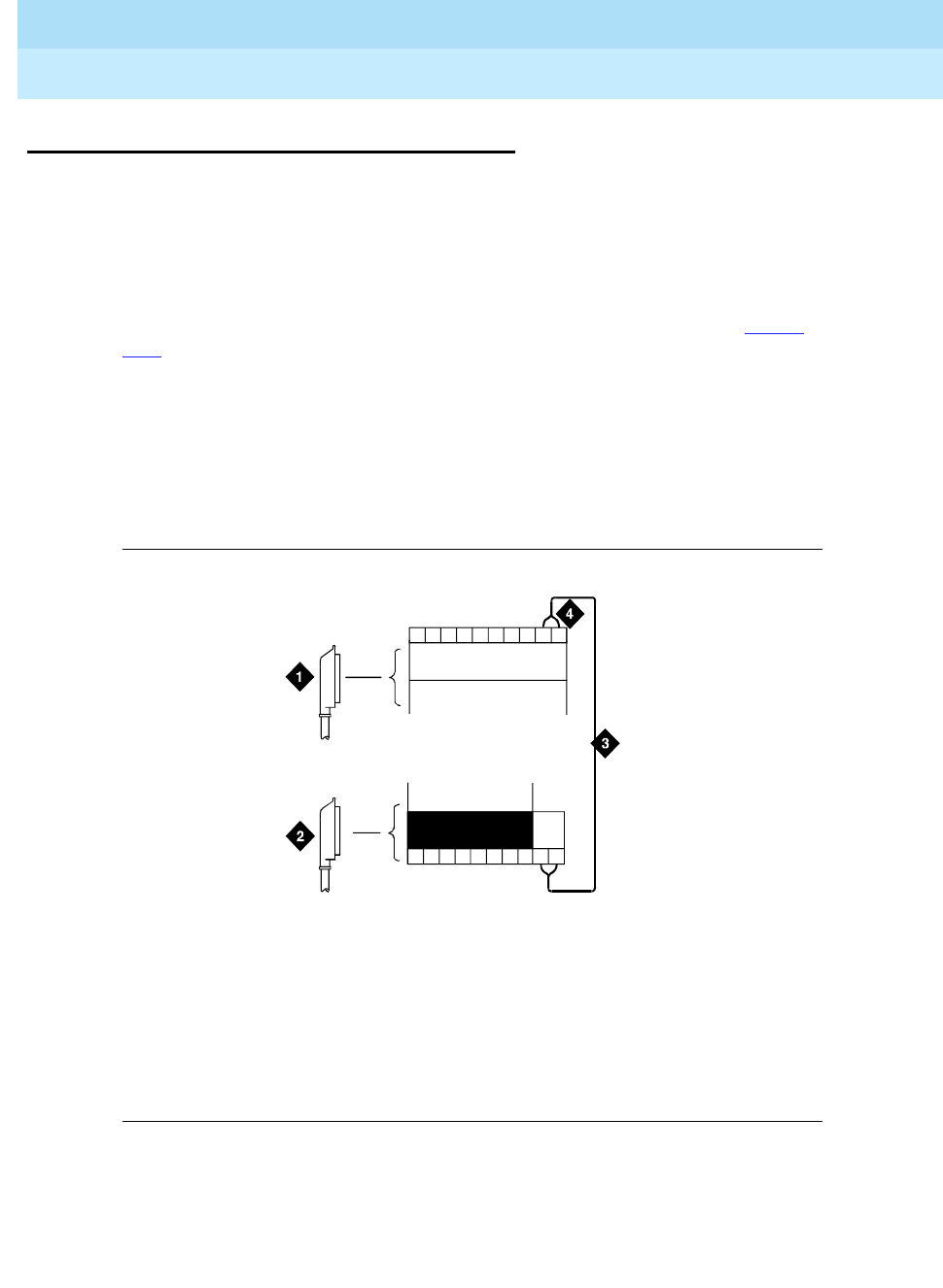
Figure 5-10. Connections at Trunk/Auxiliary Field
Figure Notes
1. To Network Interface Facility
2. To Control Carrier Auxiliary Connector
3. One Pair of Wires
4. Twenty-fifth Pair of RJ21X
Network Interface Jack
25
50
IN
r758482bRBP 062696