


DEFINITY Enterprise Communications Server Release 6
Installation and Test for Multi-Carrier Cabinets
555-230-112
Issue 5
May 1998
Install and Wire Telephones and Other Equipment
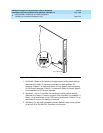
Page 5-24TN1654 DS1 Converter (Release 6r Only)
5
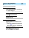
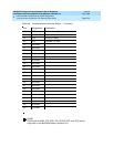
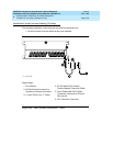
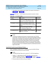
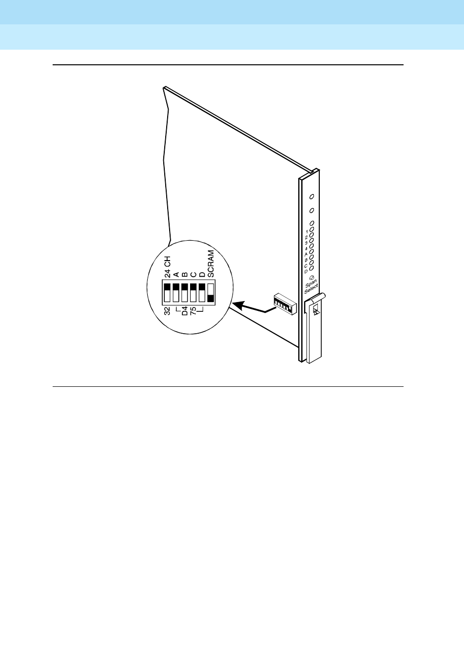
Figure 5-11. DS1 Converter Circuit Pack Switches
1. Set Switch 1 down for E1 facilities. All subsequent facility switch settings
(Switches 2-5) reflect E1 impedance on each of the 4 facilities. For
example: If Switch 1 is down and Switch 2 is up, Span A Line Impedance
of 120 Ohms is selected. If Switch 1 is down and Switch 2 is down, Span A
Line Impedance of 75 Ohms is selected.
2. Set Switch 1 up for T1 facilities. All subsequent facility switch settings
(Switches 2-5) reflect T1 framing on each of the 4 facilities. For example: If
Switch 1 is up and Switch 2 is up, ESF framing is selected. If Switch 1 is up
and Switch 2 is down, D4 framing is selected.
3. Set Switch 6 to the down (disabled) position. Switch 6 may not be present
(or active) on all TN1654 DS1 Converter circuit packs.
INSET
0015_0 RBP052396