


DEFINITY Enterprise Communications Server Release 6
Installation and Test for Multi-Carrier Cabinets
555-230-112
Issue 5
May 1998
Install and Wire Telephones and Other Equipment
Page 5-146Connector and Cable Diagrams (Pinout Charts)
5
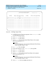
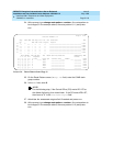
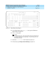
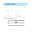
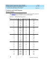
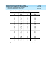
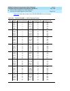
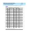
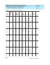
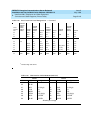
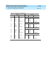
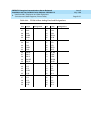
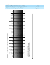
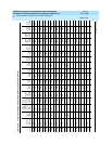
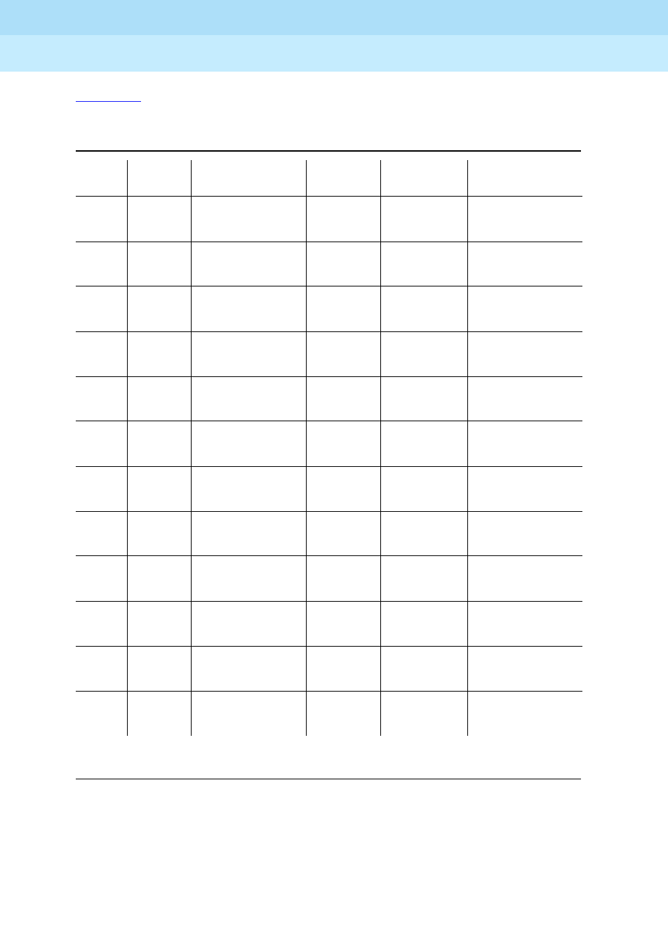
Table 5-27 shows the pinouts for the TN2198 ISDN-BRI 2-wire U Interface.
*
Pins 25 and 50 are grounded by the backplane.
Table 5-27. TN2198 ISDN-BRI — 2-Wire U Interface Pinout
Port Signal
Cross-Connect
Pin Color
Amphenol
Pin Backplane Pin
1 T.1 1 W-BL 26 102
R.1 2 BL-W 01 002
2 T.2 3 W-O 27 103
R.2 4 O-W 02 003
3 T.3 5 W-G 28 104
R.3 6 G-W 03 004
4 T.4 7 W-BR 29 105
R.4 8 BR-W 04 005
5 T.5 9 W-SL 30 106
R.5 10 SL-W 05 006
6 T.6 11 R-BL 31 107
R.6 12 BL-R 06 007
7 T.7 13 R-O 32 108
R.7 14 O-R 07 008
8 T.8 15 R-G 33 109
R.8 16 G-R 08 009
9 T.9 17 R-BR 34 110
R.9 18 BR-R 09 010
10 T.10 19 R-SL 35 111
R.10 20 SL-R 10 011
11 T.11 21 BK-BL 36 112
R.11 22 BL-BK 11 012
12 T.12 23 BK-O 37 113
R.12 24 O-BK 12 013