


DEFINITY Enterprise Communications Server Release 6
Installation and Test for Multi-Carrier Cabinets
555-230-112
Issue 5
May 1998
Connecting Fiber Optic Cables
Page A-8Optical Cross-Connect Hardware
A
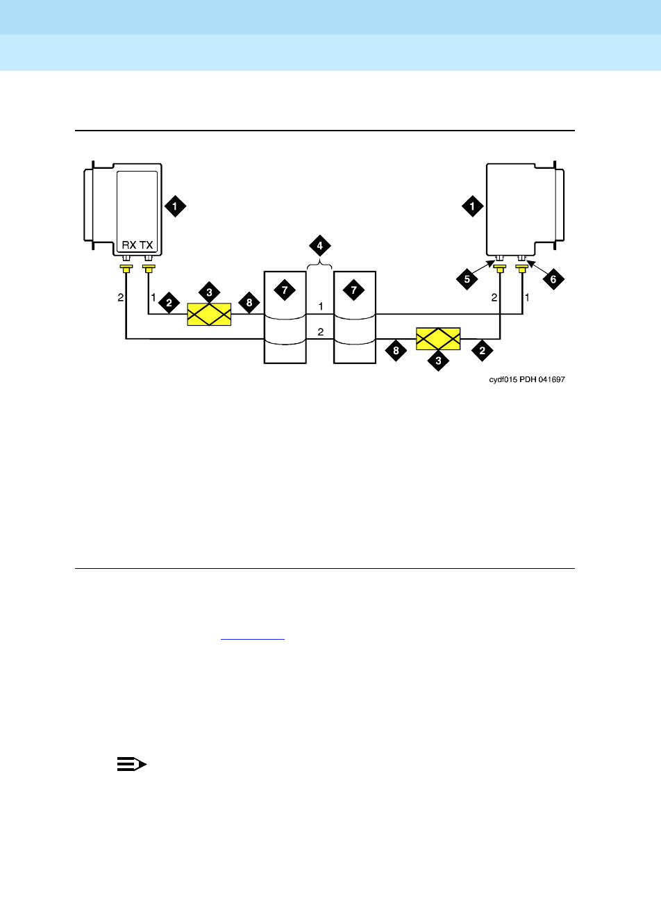
Single-Mode Fiber Link (with Attenuators)
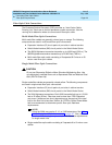
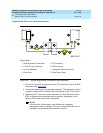
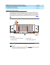
Figure A-2. Typical Single-Mode Connection with Attenuator
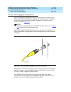
1. Connect a 2-foot (0.6 m) patchcord to the TX connector on the local 300A
transceiver. See Figure A-2
.
2. Connect the patchcord to the required attenuator. The attenuator must be
installed in series with the strand of fiber connecting to the TX connector.
3. Repeat for the TX connector at the opposite end of the fiber link (remote
EPN). A different value attenuator may be required, depending on the
amount of fiber loss back to the local system.
NOTE:
If the fiber link is duplicated, route the fiber via a separate
geographical path, if possible. This way, if the standard fiber link is
damaged, the duplicated fiber remains in service.
Figure Notes
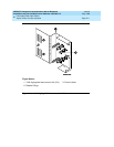
1. 300A Lightwave Transceiver
2. 2-Foot (0.6 m) Patchcord
3. In-Line Attenuator
4. Fiber Plant
5. TX Connector
6. RX Connector
7. Lightguide Interconnect Unit
8. Fiber Optic Cable