


DEFINITY Enterprise Communications Server Release 6
Installation and Test for Multi-Carrier Cabinets
555-230-112
Issue 5
May 1998
Install and Wire Telephones and Other Equipment
Page 5-19Connect Power Distribution Unit External Alarm Wires
5
Connect Power Distribution Unit
External Alarm Wires
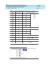
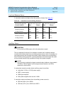
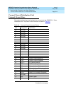
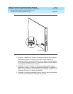
The external alarm plug should already be connected to the J58890CH-1 Power
Distribution Unit. The pinout for the connector is shown in Tab le 5- 8
.
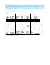
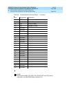
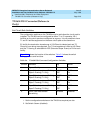
Table 5-8. External Alarm Connector Pinout
Pin Designation Definition
26 Not Used
1Not Used
27 Not Used
2Not Used
28 Not Used
3Not Used
29 Not Used
4Not Used
30 Not Used
5Not Used
31 Not Used
6Not Used
32 Not Used
7Not Used
33 RFA2 + Rectifier Failure (positive)
8 RFA2 - Rectifier Failure (negative)
34 ACF2 + AC Failure (positive)
9 ACF2 - AC Failure (negative)
35 BIF2 + Battery Interface Failure (positive)
10 BIF2 - Battery Interface Failure (negative)
36 BOD2 + Battery On Discharge (positive)
11 BOD2 - Battery On Discharge (negative)
37 Not Used
12 RXD Receive Data
38 TXD Transmit Data
Continued on next page