


DEFINITY Enterprise Communications Server Release 6
Installation and Test for Multi-Carrier Cabinets
555-230-112
Issue 5
May 1998
Install and Wire Telephones and Other Equipment
Page 5-29TN1654 DS1 Converter (Release 6r Only)
5
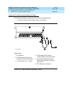
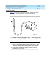
E1 Interface Cabling
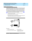
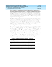
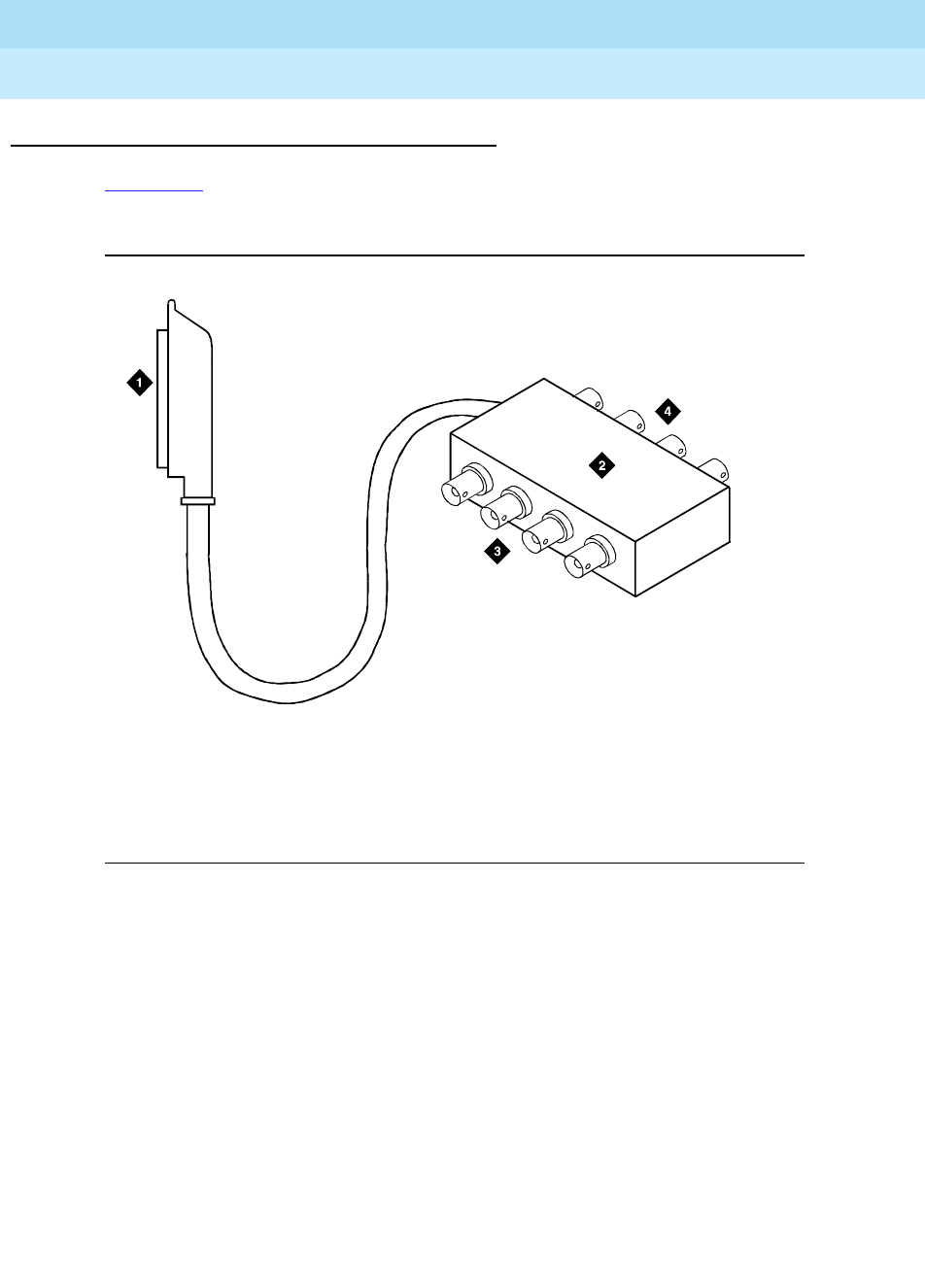
Figure 5-14 shows typical E1 cabling to the network interface via the coaxial
adapter cable. The actual adapter may be different in appearance.
Figure 5-14. DS1 Converter Connections — E1 Only
1. Connect a coaxial adapter cable to the remaining end of the “Y” cable.
The opposite end of this cable is wired to a coaxial adapter assembly.
2. Plug a customer-provided quad cable onto the 4 BNC connectors
provided on the coaxial adapter.
3. Connect the opposite end of the quad cable to the network interface.
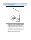
Figure Notes
1. 50-Pin Male Connector on Coaxial Adapter Cable
2. Coaxial Adapter Cable (With 8 BNC Connectors)
3. Connect to Quad Cable
4. Connect to E1 Network
0027_0RBP 061896