


DEFINITY Enterprise Communications Server Release 6
Installation and Test for Multi-Carrier Cabinets
555-230-112
Issue 5
May 1998
Install Telecommunications Cabling
Page 2-26Install Coupled Bonding Conductor
2
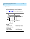
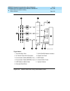
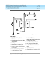
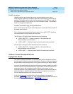
Install Coupled Bonding Conductor
The Coupled Bonding Conductor (CBC) connects to the single-point ground
block and runs adjacent to pairs in an associated telecommunications cable.
See Figure 2-15
. The mutual coupling between the CBC and the wire pairs
reduces potential differences in terminating equipment.
The conductor consists of a 10 AWG (#25) (6 mm
2
) wire tie-wrapped to the inside
wiring cable and terminated at the CBC terminal bar at the MDF. Maintain a
minimum of 12 inches (30.5 cm) spacing between the CBC and other power and
ground leads.
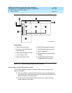
The 10 AWG (#25) (6 mm
2
) wire must be long enough to reach the
telecommunications cables at the rear of the system cabinets, follow these
cables to the MDF, and to terminate at the CBC.
1. Cut a 10 AWG (#25) (6 mm
2
) wire long enough to reach from the system’s
single-point ground block or DC power cabinet ground discharge bar to
the MDF CBC block.
2. Connect 1 end of the 10 AWG (#25) (6 mm
2
) wire to the single-point
ground block (or ground discharge bar).
3. Route the wire next to the 25-pair cables connecting to the trunk/auxiliary
(purple) field.
4. Tie wrap the 10 AWG (#25) (6 mm
2
) wire to the 25-pair cables.
5. Connect the 10 AWG (#25) (6 mm
2
) wire to the MDF CBC ground block.
6. Repeat the above steps for each CBC ground wire.