


DEFINITY Enterprise Communications Server Release 6
Installation and Test for Multi-Carrier Cabinets
555-230-112
Issue 5
May 1998
Install and Wire Telephones and Other Equipment
Page 5-10Auxiliary Connector Outputs
5
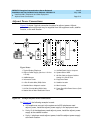
Auxiliary Connector Outputs
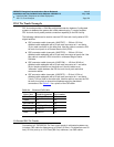
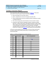
The control carrier output cable pinouts are shown in Table 5-2. The control
carrier AUX connector outputs include the following:
■ Alarm monitoring for the auxiliary cabinet.
■ Seven -48 VDC power sources for emergency transfer units.
■ Three -48 VDC power sources for remotely powering 3 attendant consoles
or telephone adjuncts.
■ The remote management terminal interface trunk connection location.
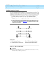
■ Access to a relay contact is available to actuate a customer-provided
light, bell, or similar alarm device. Administer the system to make contact
when a major, minor or warning alarm condition occurs in the system. The
circuitry required for this feature is customer-provided. The device
connected to the alarm leads must not exceed a rating of 30 VAC RMS or
60 VDC at 0.75 Amps. See Tab l e 5 -2
for the pinouts for an external alarm.
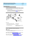
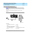
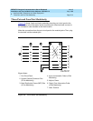
A 25-pair connector labeled AUX is provided on the rear of the control carrier.
Connect a cable to this connector and route to a connecting block on the
trunk/auxiliary field.
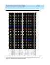
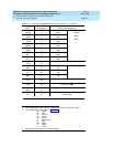
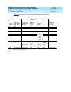
Table 5-2. Auxiliary Lead Appearances at AUX Connector
Color
1,2
Pin Number AUX Connector Outputs
W-BL
BL-W
26
1
Major
3
W-O
O-W
27
2
Minor
3
W-G
G-W
28
3GRD
W-BR
BR-W
29
4GRD
W-S
S-W
30
5GRD
R-BL
BL-R
31
6GRD
R-O
O-R
32
7GRD
R-G
G-R
33
8
Not Connected
R-BR
BR-R
34
9
Not Connected
R-S
S-R
35
10
Not Connected
Continued on next page