


DEFINITY Enterprise Communications Server Release 6
Installation and Test for Multi-Carrier Cabinets
555-230-112
Issue 5
May 1998
Cable Ductwork
Page C-16
C
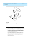
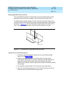
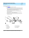
Install I/O Cable Rack Riser
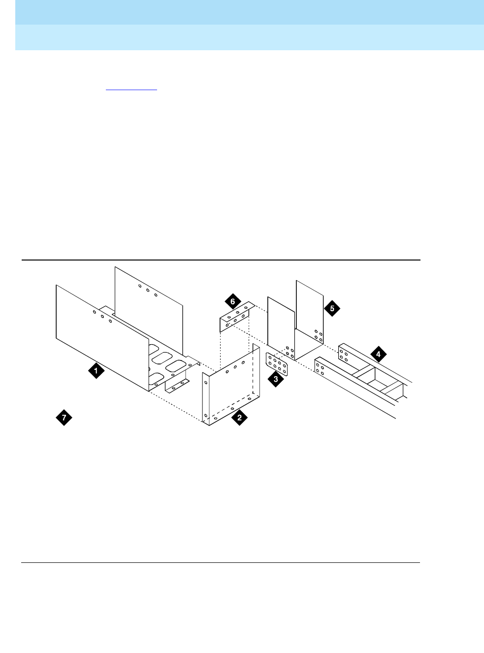
Refer to Figure C-11 and assemble the ductwork:
1. Attach angle bracket (group 9) to I/O trough using thread-forming screws.
2. Attach cross-aisle bracket to angle bracket using thread-forming screws.
Attach the angle bracket to the 6-hole face of the cross-aisle bracket using
three thread-forming screws through the bottom holes.
3. Attach I/O coupling trough (group 8) to cross-aisle bracket using
thread-forming screws.
4. Attach cable rack to coupling trough using locally-provided coupling
plates and 3/8-18 x 1/2 inch hex bolts and nuts.
5. Attach other end of cable rack to wall using locally provided hardware
suitable to type of wall.
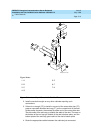
Figure C-11. Installation of I/O Cable Rack Riser to End of Cabinet (Group 9)
Figure Notes
1. I/O Trough
2. Angle Bracket
3. Coupling Plate
4. Cable Rack
5. I/O Coupling Trough
6. Cross-Aisle Bracket
7. Front of Cabinet
duct7 KLC 071796