DEFINITY Enterprise Communications Server Release 6
Installation and Test for Multi-Carrier Cabinets
555-230-112
Issue 5
May 1998
Connector and Cable Diagrams
Page D-3
D
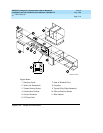
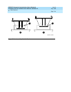
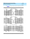
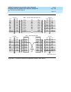
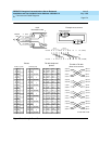
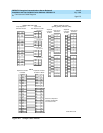
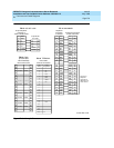
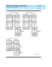
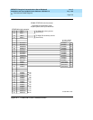
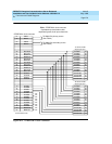
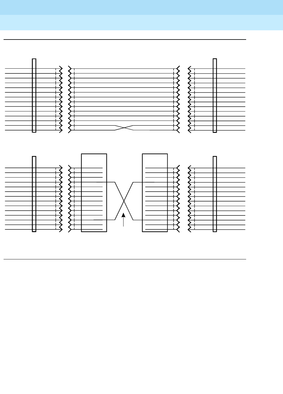
Figure D-2. Expansion Interface to Expansion Interface Fiber (Part 2)
Front Front
Rear Rear
Backplane Backplane
Front Front
Rear Rear
Backplane Backplane
+5V
+5V
GRD
XMT_DAT
GRD
GRD
TA *
TL*
GRD
GRD
GRD
RCV_DAT
+5V
+5V
(P1) 1
(P1) 26
(P1) 2
(P1) 27
(P1) 3
(P1) 28
(P1) 4
(P1) 29
(P1) 5
(P1) 30
(P1) 6
(P1) 31
(P1) 7
(P1) 32
9823A/B
(P1) 1
(P1) 26
(P1) 2
(P1) 27
(P1) 3
(P1) 28
(P1) 4
(P1) 29
(P1) 5
(P1) 30
(P1) 6
(P1) 31
(P1) 7
(P1) 32
9823A/B
SNI SNI
FS 5 - SNI to SNI fiber cable
Fiber
+5V
+5V
GRD
XMY_DAT
GRD
GRD
TA*
TL*
GRD
GRD
GRD
RCV_DAT
+5V
+5V
000
100
001
101
002
102
003
103
004
104
005
105
006
106
000
100
001
101
002
102
003
103
004
104
005
105
006
106
+5V
+5V
GRD
GRD
GRD
TA *
TL*
GRD
GRD
GRD
+5V
+5V
XMT_DAT
RCV_DAT
+5V
+5V
GRD
GRD
GRD
TA *
TL*
GRD
GRD
GRD
+5V
+5V
002
102
003
004
104
005
105
006
106
007
008
108
103
107
002
102
003
004
104
005
105
006
106
007
008
108
103
107
(J2) 1
(J2) 26
(J2) 2
(J2) 3
(J2) 28
(J2) 4
(J2) 29
(J2) 5
(J2) 30
(J2) 6
(J2) 7
(J2) 32
(J2) 27
(J2) 31
(J1) 1
(J1) 26
(J1) 2
(J1) 3
(J1) 28
(J1) 4
(J1) 29
(J1) 5
(J1) 30
(J1) 6
(J1) 7
(J1) 32
(J1) 27
(J1) 31
EI EI
FS 4 - EI to EI metallic cable H600-278
+5V
+5V
GRD
GRD
GRD
TA*
TL*
GRD
GRD
GRD
+5V
+5V
XMT_DAT
RCV_DAT
r975bb1b MMR 061396


