


DEFINITY Enterprise Communications Server Release 6
Installation and Test for Multi-Carrier Cabinets
555-230-112
Issue 5
May 1998
Cable Ductwork
Page C-4
C
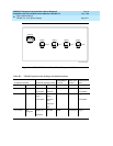
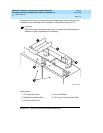
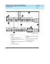
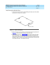
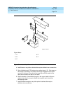
Install the various cable ducts in the order shown in Tab l e C -2. Figure C-2 shows
an overhead view of a typical ductwork installation.
!
WARNING:
To prevent damage to the cabinet circuitry or cables, place cardboard or
equivalent in the cable ducts to catch any metal filings that may fall from the
self-threading screws.
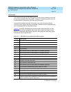
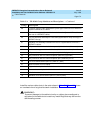
28 Transition between older DIMENSION system-type cabinet and new DEFINITY
system cabinets for I/O cables
29 Shielded duct assembly transition from the front of a System 85-R1 cabinet to
the rear of a DEFINITY cabinet
30 I/O duct transition assembly for cross-aisle (System 85-R1 lineup to bridge a
DEFINITY lineup)
31 Shielded duct assembly transition from rear of a System 85-R1 to front of a
DEFINITY cabinet
32 AC power with a 4-wire twist-lock receptacle (left side viewed from rear)
33 Ladder rack supported 86 or 88.5 inches (218.4 cm or 224.7 cm) from floor
34 AC power duct with two 3-wire receptacles (250 VAC) (right side)
35 AC power duct with one 3-wire receptacle (250 VAC) (right side)
37 AC power duct with one 3-wire receptacle (30 A, 208 VAC) for CC
39 I/O cross-aisle ductwork (48 inch (109.2 cm ) aisle)
41 Basic hardware for one cabinet
42 Right or left end plate for shielded ductwork
44 Front and rear end plate for shielded ductwork
51 Shielded cross-aisle ductwork
78 Shielded cross-aisle ductwork (48 inch (122 cm) aisle)
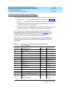
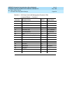
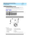
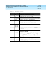
Table C-1. ED-1E465 Group Numbers and Descriptions — Continued
Group Description
Continued on next page