


DEFINITY Enterprise Communications Server Release 6
Installation and Test for Multi-Carrier Cabinets
555-230-112
Issue 5
May 1998
Install and Connect Cabinets
Page 1-36Earthquake Protection Installation
1
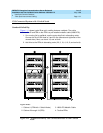
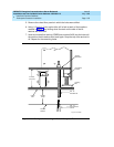
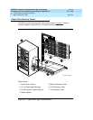
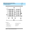
8. A 3/8-16 threaded rod (part number 845557073) is used to secure the
cabinet to each concrete floor anchor. See Figure 1-14
.
Measure the distance from 1 of the anchors to the bottom of the cabinet.
Add 1/2-inch (1.3 cm) to this measurement to allow the rod to be threaded
into the floor anchor. Add an additional 1/2-inch (1.3 cm) to allow the rod
to protrude up through the bottom of the cabinet. For example: if the
distance from the floor anchor to the bottom of the cabinet is 10 inches (25
cm), cut the threaded rod 11 inches (27.9 cm) long.
9. When all 4 threaded rods are cut, replace the raised floor panels removed
in Step 5.
10. Position the cabinet over the holes and adjust the leveling legs until the
cabinet is level.
NOTE:
If the system is supplied with cable ductwork, the cabinets must be
level from front to rear and from side to side. They must be square
with respect to each other to within +-1/8-inch (0.3 cm).
11. Insert the threaded rods through the cabinet bottom and thread into the
concrete floor anchors.
12. Place a 3/8-inch flat washer onto each rod. Thread a 3/8-16 hex nut onto
each rod and tighten securely.
13. Repeat this procedure for each cabinet to be installed (including the
Auxiliary Cabinet and the Stratum 3 Clock Cabinet).